Table of Contents
Advertisement
Quick Links
INSTALLATION, COMMISSIONING AND SERVICING INSTRUCTIONS
WALL HUNG RSF GAS FIRED CONDENSING REGULAR BOILER
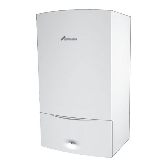
GREENSTAR CDi CLASSIC REGULAR
FOR OPEN VENTED AND SEALED CENTRAL HEATING SYSTEMS AND INDIRECT DOMESTIC HOT WATER
THE APPLIANCE IS FOR USE WITH NATURAL GAS OR L.P.G.
(Cat II 2H3P TYPE C13 & C33)
NATURAL GAS:
30CDi Classic Regular
40CDi Classic Regular
LIQUID PETROLEUM GAS:
30CDi Classic Regular
40CDi Classic Regular
UK/IE
ErP
ErP
GC Number 41-406-33
ErP
GC Number 41-406-35
ErP
GC Number 41-406-34
ErP
GC Number 41-406-36
Advertisement
Table of Contents


Need help?
Do you have a question about the Worcester GREENSTAR CDi CLASSIC REGULAR ErP Series and is the answer not in the manual?
Questions and answers