Table of Contents
Advertisement
Quick Links
Advertisement
Table of Contents

Related Manuals for UfiSpace S9180-32X


Summary of Contents for UfiSpace S9180-32X
- Page 1 S9180-32X 100G Data Center Switch Hardware Installation Guide R1.1...
-
Page 2: Table Of Contents
Fan FRU LED ......................... 19 11 Initial System Setup ......................20 12 Cable Connections ......................21 Connecting the USB Cable ....................21 Connecting the Transceivers ....................21 13 Cautions and Regulatory Compliance Statements .............. 22 S9180-32X Hardware Installation Guide | i... -
Page 3: Overview
Ethernet switching market and the needs to push capacity to the next level. With 32 x 100G QSFP28 ports, the S9180-32X switch is where computer resources (servers or blade chassis) are centralized and managed in a structured way utilizing high-efficiency Ethernet connectivity. -
Page 4: Preparation
PC with terminal emulation software. Refer to the "Initial System Setup" section for details. • Baud rate: 115200 bps • Data bits: 8 • Parity: None • Stop bits: 1 • Flow control: None Illustrations are for reference purposes only. Actual equipment and scenarios may differ. S9180-32X Hardware Installation Guide | 2... -
Page 5: Installation Environment Requirements
Space Clearance: The S9180-32X width is 17.32 inches (44.0cm) and shipped with a rack mount brackets suitable for 19 inch (43.8cm) wide racks. The depth of the S9180-32X chassis is 16.9 inches (42.8cm) without the field replaceable units (FRUs) and comes with adjustable mounting rails suitable for rack depths of 24 inches (60.9cm) to 31 inches (78.7cm). -
Page 6: Preparation Check List
• Cooling: The S9180-32X has two options for airflow direction. There is a back-to-front option (Figure 3. Left) and a front-to-back option (Figure 3. Right). Make sure the equipment on the same rack have the same airflow direction. Back-to-Front Airflow Front-to-Back Airflow Figure 3. -
Page 7: Package Contents
1.03lb (470g)/2pcs 78.74” (6.56’)(2000mm) 2 pcs (AC Version only) 0.51lb (235g)/pcs Power Cord 2.72lb (1234g)/2pcs 118.11”(9.8’) (3000mm) 2 pcs (DC Version only) 1.36lb (617g)/pcs RJ45 to DB9 Female 95.98” (2438mm) 1 pcs 0.23lb (105g)/pcs Cable S9180-32X Hardware Installation Guide | 5... -
Page 8: Component Physical Information
AC power cord (AC version only) 0.51lbs (235g) RJ45 to DB9 female cable 0.23lbs (105g) S9180-32X (W x D x H) 17.32” x 16.88” x 1.73” (440 x 428.8 x 44mm) Dimension PSU (W x D x H) 2.89” x 7.28” x 1.57” (73.5 x 185 x 40mm) Fan module (W x D x H) 2.18”... -
Page 9: Identifying Your System
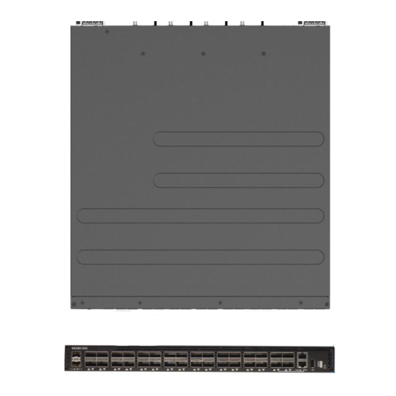
4 Identifying Your System S9180-32X System Overview Figure 5. S9180-32X Hardware Installation Guide | 7... -
Page 10: Dc Version Psu Overview
The DC power supply units are the same size for both back-to-front airflow and front-to-back airflow. Therefore, only the dimensions for front-to-back airflow PSU will be provided in the figure below. (Front-to-Back Airflow PSU) Figure 7. S9180-32X Hardware Installation Guide | 8... -
Page 11: Ac Version Psu Overview
The AC power supply units are the same size for both back-to-front airflow and front-to-back airflow. Therefore, only the dimensions for front-to-back airflow PSU will be provided in the figure below. (Front-to-Back Airflow PSU) Figure 9. S9180-32X Hardware Installation Guide | 9... -
Page 12: Fan Overview
(Back-to-Front Airflow Fans) (Front-to-Back Airflow Fans) Figure 10. Port Overview Port ID Form Factor Maximum Support Distance Support Speed 1 ~ 32 QSFP28 6.21mi (10km) 40/100G 33 ~ 34 SFP+ 6.21mi (10km) 1/10G Figure 11. S9180-32X Hardware Installation Guide | 10... -
Page 13: Rack Mounting
For a 4 post rack, first secure the adjustable mounting rail to the back of the switch using the M4.0*L6.5mm screws provided in the package. Then secure the adjustable mounting rail to the rack posts. Figure 14. S9180-32X Hardware Installation Guide | 11... -
Page 14: Installing Fan Modules
4. Carefully slide the new fan module into the fan bay and gently push until it is flush with the case. 5. Secure the captive screw on the fan module to lock the fan in place. Figure 17. S9180-32X Hardware Installation Guide | 12... -
Page 15: Installing Power Supply Units
3. Align the new PSU with the power bay, ensuring the PSU’s power connector is in the correct position. 4. Carefully slide the new PSU into the power bay and gently push until it is flush with the case. S9180-32X Hardware Installation Guide | 13... - Page 16 5. An audible click will be heard when the PSU is installed correctly. The PSU will not go in all the way if it is in the wrong direction. Illustrations are for reference purposes only. Actual PSU position may differ. DC Version: AC Version: Figure 20. S9180-32X Hardware Installation Guide | 14...
-
Page 17: Grounding The Switch
2. Remove the grounding screw from the switch. 3. Attach the power cable Connect the screw to an 18AWG minimum ring terminal grounding wire (not provided). 4. Connect the other end of the wire to the rack ground. Figure 21. S9180-32X Hardware Installation Guide | 15... -
Page 18: Connecting Power
Also, please ensure that both PSUs have been properly installed before powering up the equipment, as the S9180-32X is designed to support 1 + 1 power redundancy. 2. Attach the power cable. -
Page 19: Ac Version
Also, please ensure that both PSUs have been properly installed before powering up the equipment, as the S9180-32X is designed to support 1 + 1 power redundancy. 2. Attach the power cable. -
Page 20: Verifying System Operation
PSU FRU LED Additional information about PSU status can be obtained by the LEDs located on the PSU itself. LED Condition Equipment Status No input power to all power supplies. Green Output ON and OK S9180-32X Hardware Installation Guide | 18... -
Page 21: Fan Fru Led
Fan FRU LED LED Condition Equipment Status No input power Solid Green Fan is functioning normal Solid Amber Fan is abnormal, service is required S9180-32X Hardware Installation Guide | 19... -
Page 22: Initial System Setup
After the connection is established, a prompt for the username and password displays. Enter the username and password to access the CLI. The username and password should be provided by the Network Operating System (NOS) vendor. S9180-32X Hardware Installation Guide | 20... -
Page 23: Cable Connections
3. Place the bail (wire handle) in the unlocked position and align the transceiver with the port. 4. Slide the transceiver into the port and use gentle pressure to secure it in place. An audible click can be heard when the transceiver is secured in the port. S9180-32X Hardware Installation Guide | 21... -
Page 24: Cautions And Regulatory Compliance Statements
The equipment and its modules should only be repaired, maintained or replaced by skilled personnel. Instructed person is a term applied to persons who have been instructed and trained by a skilled person, or who is supervised by a skilled person. S9180-32X Hardware Installation Guide | 22... - Page 25 www.ufispace.com...
Need help?
Do you have a question about the S9180-32X and is the answer not in the manual?
Questions and answers