Sinexcel PWS1-500K Series Operating Manual
Energy storage pcs
Hide thumbs
Also See for PWS1-500K Series:
- Installation manual (39 pages) ,
- Installation manual (75 pages)
Table of Contents
Advertisement
Advertisement
Table of Contents
Troubleshooting

Related Manuals for Sinexcel PWS1-500K Series


Summary of Contents for Sinexcel PWS1-500K Series
- Page 1 Operating Manual PWS1-500K Series Energy Storage PCS...
- Page 2 Sinexcel PWS1-500KTL-EX-1M/2M/3M/4M/5M/6M/7M/8M PWS1-500KTL-EX-M1/M2/M3/M4/M5/M6/M7/M8 Series Bi-directional Energy Storage PCS Operating Manual Version: V2.1 Shenzhen Sinexcel Electric Co., Ltd. All rights reserved. In case of any content change, it shall be without prior notice. Shenzhen Sinexcel Electric Co., Ltd. Website: http://sinexcel.us/ www.sinexcel.com Add: Building 6, Area 2, Baiwangxin High-tech Industrial Park, No.
-
Page 3: Table Of Contents
Table of Contents 1 Information on this Document........................4 1.1 Validity ............................... 4 1.2 Target Group ............................4 1.3 Nomenclature Terms and abbreviations ....................5 2 Safety Precautions ............................. 6 2.1 Symbols ............................. 6 2.2 Important Safety instructions ....................... 7 2.3 Additional Information ......................... - Page 4 8.3 Setting Procedure before startup ....................... 44 8.3.1 Touch screen power on ....................... 44 8.3.2 Log into the control Interface ...................... 45 8.3.3 Select Control Mode ........................45 8.3.4 General Settings ......................... 46 8.3.5 Communication setting ....................... 46 8.4 Manual Startup Procedure ......................... 46 8.5 Automatic Startup Procedure ......................
-
Page 5: Information On This Document
1 Information on this Document 1.1 Validity This document is valid for the following device models with or without STS module: • PWS1-500K • PWS1-500KTL • PWS1-500KTL-EX-1M/2M/3M/4M/5M/6M/7M/8M • PWS1-500KTL-EX-M1/M2/M3/M4/M5/M6/M7/M8 Model definition This section introduces product model definition in this operating manual, as shown in Fig. 1-1: PWS1- 500KTL-EX-XM XM: Module number :... -
Page 6: Nomenclature Terms And Abbreviations
1.3 Nomenclature Terms and abbreviations Terms Definition Static Transfer Switch Alternative current. Direct current. BESS Battery energy storage system Energy storage system. Energy management system. Battery management system. Power conversion system. Single line diagram State of health (of battery), expressed in percentage. Silicon controlled rectifier Depth of discharge, the rest battery capacity, expressed in percentage. -
Page 7: Safety Precautions
2 Safety Precautions 2.1 Symbols NO. Symbol Reference Standard Description IEC 60417-5036 Note the shock hazard, IEC 60417-5416 energy storage time release (discharge time is marked next to the symbol) ISO 7000-0434 Watch out for danger IEC 60417-5041 Watch surface ISO 7000-1641 Refer to the operation manual... -
Page 8: Important Safety Instructions
NOTE is used to address information that is not related to pers onal injury, equipment damage, and environmental degradation. 2.2 Important Safety instructions This user’s manual is about installation and operation of Sinexcel PWS1 series 500kW Bi-directional Energy Storage Inverter (PCS). Before installation, please read this user’s manual carefully. -
Page 9: Additional Information
The components behind the protective cover plate and dam board which are opened by tools cannot be maintained by users. Please read this user’s manual before operation. 2.3 Additional Information Links to additional information can be found at http://sinexcel.us/ or www.sinexcel.com. -
Page 10: Product Introduction
This kind of PCS can be used in the on-grid mode and off-grid mode. The model with STS can get the faster switching between on-grid and off-grid mode. The [PWS1-500K series Bi-directional Storage Inverter (PCS)] can be used in off-grid systems based on diesel generators (Gensets). - Page 11 Both models have identical mechanical and electrical construction except composed of different sets of PCS-AC modules and rating: For PWS1-500K series is composed of 8 sets of PCS-AC modules, the special model with different number of DC branch switches from 1 to 8.
-
Page 12: Pcs Composition
components. PCS-AC module 8 set(s) Power Management Unit 1 set It is installed in the cabinet door. 3.4 PCS Composition Figure3-3: Visible Components of the PCS without STS module with STS module Position Designation Description Indicator lights Touch Screen EPO (Emergency Power Off) PCS-AC (1~8 module(s)) 62.5KW 1 set Battery DC Branch Switch... -
Page 13: Operating Compositions
3.5 Operating Compositions 3.5.1 Switches Introduction 3.5.1.1 AC switch The AC disconnection unit disconnects the PCS from the Grid. The NA series PCS breaker is comply to the UL certification. ▽ ▽ ▽ ▽ Figure 3-4: Switch positions of the AC disconnection unit Position Designation Explanation... -
Page 14: Touch Screen
3.5.1.3 AUX power supply AC Switch 220Vac AUX power supply can be the redundancy power supply through the AC Switch inside the PCS cabinet. These switches can be visible after opening the dam-board. AUX power supply switch SPD switch Figure 3-6: AUX power supply AC Switch and SPD switch 3.5.2 Touch Screen 3.5.2.1 User Interface The touch display is used to display instantaneous values and parameter settings. -
Page 15: Leds Of The System
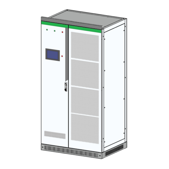
Position Designation Explanation Menu Menu can be different before/after log-in and other setting. System Topology Version and time 3.5.2.2 Symbols Explanation Symbol Designation Grid Load in AC side DC side STS Module Transformer (Inside) AC Module Switch on DC or AC side open Switch on DC or AC side closed 3.5.3 LEDs of the System The appearance of the PCS is shown in below. -
Page 16: Labels
Figure 3-9 Front view for PCS-AC module LED designation Description Explanation Normal indicator light Green Fault indicator light DIP switch Address Hanger Power supply socket Communication cable socket Handle Can’t bearing too much weight 3.5.4 Labels Figure 3-11 Warning label position... - Page 17 Label Explanation Label-Dot label-A phase Label-Dot label-B phase Label-Dot label-C phase Label-Dot label-Negative electrode Label-Dot label-Negative electrode Label-Dot label-Negative electrode Label-Dot label-Neutral line Label-Dot label-Grounding Label-Warning label-Danger High Voltage Label-Warning label-Danger large leak current...
-
Page 18: Technical Data
4 Technical Data Technical parameters for the models without transformer (500KTL series) Specification PWS1- PWS1- PWS1- PWS1- PWS1- PWS1- PWS1- PWS1- Model 500KTL 500KTL- 500KTL 500KTL 500KTL- 500KTL- 500KTL- 500KTL- -EX-8M EX-7M -EX-6M -EX-5M EX-4M EX-3M EX-2M EX-1M Utility-interactive Mode Battery voltage 600~900V... - Page 19 current(rms) Current(inrush) Maximum output 1080A 945A 810A 675A 540A 405A 270A 135A fault current Maximum output 1080A 945A 810A 675A 540A 405A 270A 135A overcurrent protection Nominal power 500kVA 437.5kVA 375kVA 312.5kVA 250kVA 187.5kVA 125kVA 62.5Kva AC max power 550kVA 481.2kVA 412.5kVA 343.8kVA...
- Page 20 Over voltage category Specification PWS1- PWS1- PWS1- PWS1- PWS1- PWS1- PWS1- PWS1- Model 500KTL- 500KTL- 500KTL- 500KTL- 500KTL 500KTL- 500KTL- 500KTL- EX-M8 EX-M7 EX-M6 EX-M5 -EX-M4 EX-M3 EX-M2 EX-M1 Utility-interactive Mode Battery voltage 600~900V range Battery Normal 750V voltage DC max current 873A 763A 654A...
- Page 21 Current (inrush) Maximum output 1080A 945A 810A 675A 540A 405A 270A 135A fault current Maximum output 1080A 945A 810A 675A 540A 405A 270A 135A overcurrent protection Nominal power 500kVA 437.5kVA 375kVA 312.5kVA 250kVA 187.5kVA 125kVA 62.5kVA AC max power 550kVA 481.2kVA 412.5kVA 343.8kVA 275kVA...
- Page 22 Over voltage category The default PCS configuration is without the transformer, when the buyer needs the special model with the isolation transformer, the buyer should confirm the transformer provided by the manufacture to meet the local certification requirement of the application location. Technical parameters for the models with transformer (500K series) Model PWS1-500K...
- Page 23 105%~115% 10min; Overload Capability 115%~125% 1min; 125%~150% 200ms Physical Cooling Forced air cooling Noise 70dB Enclosure IP20 Max elevation 3000m/10000feet (> 2000m/6500feet derating) Operating ambient temperature -20°C to 50°C (De-rating over 45°C ) Humidity 0~95% (No condensing) Size (W×H×D) 2200×2160×800mm Weight 2000kg Installation...
-
Page 24: Storing, Lifting And Transporting
5 Storing, lifting and transporting More detailed shipping and installation information can be found in the Installation Manual. 5.1 Safety during Transport If the lifted or suspended load falls over, falls or sways, there is a risk of crushing Vibration or careless or hasty lifting and transport can cause the product to tip over or fall. This can result in death or serious injury. -
Page 25: Installation
6 Installation More detailed shipping and installation information can be found in the installation manual. 6.1 Safety during Installation Risk of electric shock caused by live voltage. There is a high voltage in the live components of the product. Touching field components can result in death or seriousness electric shock damage. -
Page 26: Mechanical Installation
The PWS1-500K cabinet, width: 1100mm, height: 2,100mm (without lifting rings); depth: 800mm. The height of the lintel is 60mm and it can be taken down if there is no sufficient height into the room. The PWS1-500K series Storage Inverter is without lifting rings and can’t lift. -
Page 27: Preparation For Mounting On A Base
Fig. 6-2 PWS1-500K rack wiring hole in bottom view There are two holes in each corner, only one hole needs to mount bolts, the other hole is used as a spare. 6.2.2 Preparation for Mounting on a Base After the rack is removed to the installation position of BESS (battery energy storage system) with a forklift or a tool. -
Page 28: Output Requirement
For the multi-string models. Every DC input circuit branch in PCS should be able to operate independently. For multi-string models (e.g. PWS1-500KTL-XX), each DC input is independent from the other and should be connected with individual battery system. The batteries need to be connected to each branch port. 6.3.2 Output requirement The output of the PCS is 3-phase . - Page 29 Open the dam-board of back door and then can see the wiring copper bar as shown below. Back View 3D View Fig. 6-3 PWS1-500K series with 1 branch DC input cabinet wiring copper bars designation...
- Page 30 Table 6-3 PWS1-500K series with 1 branch DC input cabinet wiring copper bars description Position Designation Description Battery + Battery input positive pole Battery - Battery input negative pole Phase A, dimension is shown as below. Phase B Phase C Fig.
- Page 31 Front View 3D View Fig. 6-6 PWS1-500K series with 4 branch DC input cabinet wiring copper bars designation...
- Page 32 Table 6-4 PWS1-500K series with 4 branch DC input cabinet wiring copper bars description Position Designation Description Battery + Battery positive port Battery + Battery positive port Battery - Battery negative port Battery - Battery negative port Battery + Battery positive port...
- Page 33 Front View 3D View Fig. 6-7 PWS1-500K series with 8 branch DC input cabinet wiring copper bars designation...
- Page 34 Table 6-5 PWS1-500K series with 8 branch DC input cabinet wiring copper bars description Position Designation Description Battery + Battery positive port Battery + Battery positive port Battery - Battery negative port Battery - Battery negative port Battery + Battery positive port...
-
Page 35: System Grounding
Fig. 6-9 PWS1-500K series AC wiring copper bars dimension 6.3.4 System grounding The modules in the PCS realize grounding connection with the rack through hangers. As for rack grounding, the rack bottom is installed with grounded cooper bars. During wiring, refer to the following table for cable diameter. -
Page 36: Ac Port Wiring
wiring. The positive and negative poles of batteries cannot be connected inversely. Before wiring, a multi-meter needs to be used for measurement. 6.3.6 AC port wiring The AC port wiring should be done before power on, the detailed DC port wiring could be seen in installation manual. - Page 37 Table 6-6 Communication interface description Interface position Description Explanation Terminal strip ports RS485 , CAN, DI, DO, AUX power Shown as 6.3.7 Wiring of terminal strips Touch Screen Ethernet port Shown as 6.4 Communication interface Fig. 6-11 Definition of terminal strip ports B M S F a u l t s S i g n a l E x t e r n a l E P O N o r m a l C l o s e R e s e r v e d...
- Page 38 External EPO Normal Open Fig. 6-13 Definition of additional terminal strip ports for 1 branch DC Input Switch BMS Faults Signal 1 BMS Faults Signal 2 BMS Faults Signal 3 BMS Faults Signal 4 BMS Faults Signal 5 BMS Faults Signal 6 BMS Faults Signal 7 BMS Faults Signal 8 External EPO Normal Open...
-
Page 39: Communication Interface Connection
6.4.1 Connecting the EMS over RS485 or Ethernet Sinexcel’s PCS has several different communication interfaces: Ethernet, RS-485 and CAN. When connecting to the Sinexcel or other brand EMS, the communication port is default as RS 485 as shown below. The Ethernet communication port can also used to connecting EMS according to the requirements for certain project. -
Page 40: Connecting A Bms Over Can
If the BMS use Ethernet communication port, a Ethernet-CAN protocol converter is needed . That Ethernet-CAN protocol converter should be bought by the user and its beyond Sinexcel’s scope of supply. The PCS communicates with battery management unit (BMS) to monitor battery state information, give an alarm and provide fault protection for battery according to the battery state and improve the safety of storage battery. -
Page 41: Check After Installation
Fig. 6-17 PCS CAN communication terminal 6.5 Check after installation After installation of PCS, please inspect all aspects according to the checklist in the Installation Manual. Any failure to complete the checklist might void the warranty. -
Page 42: Function Description
7 Function Description 7.1 Operating Status 7.1.1 Overview of the Operating Status Powered Off status Power On procedure Power Off procedure Powered up status Stop status Setting and startup Shut down procedure procedure Or Faults occurred Operation status Including: Off-grid Operation On-grid Operation Fig. -
Page 43: Operating States Without Sts
7.1.2 Operating States without STS After external wiring of the storage inverter is completed, and wiring is fully checked, close the breaker in AC port. The storage inverter can be switched in different modes under the conditions below. Without STS Module Powered up Stop running when switching between On-grid and off-grid... -
Page 44: Operation
8 Operation 8.1 Safety during Operation DC side operation is disturbed due to incorrect parameter settings When setting the mode of the AC side, please make sure that the control parameter is consistent with the grid requirement. 8.2 Power On Procedure Power on for the first time: 1): Confirm the DC and AC cable firmly connected according to the check list in the Installation Manual. -
Page 45: Setting Procedure Before Startup
Powered Off Step 1.Closing AUX Power supply switch Step 2. Closing SPD switch Step 3. Closing AC breaker (Grid) Step 4.Closing battery switch Powered up Fig. 8-2 Power on sequence for the PWS1-500KTL series PCS without transformer. 8.3 Setting Procedure before startup 8.3.1 Touch screen power on After auxiliary power of the storage inverter is connected, THE HMI is on. -
Page 46: Log Into The Control Interface
Fig. 8-4 Main Interface Sample Detailed Menu information can be seen in Appendix. “11.1 Touch Screen Startup” 8.3.2 Log into the control Interface 1. Select “User”, Log into the control interface on touch screen with password. 2. User can get the password from the authorized person/ party / agency/ etc. The login password 123456789 can obtain administrator authority. -
Page 47: General Settings
8.3.4 General Settings Fig. 8-5 Setting Interface Sample There are General Setting and Advanced Setting, the commonly used setting is in the “General” Users should set the “DC Configuration” according to the voltage and current requirement of BMS. The detailed advanced setting can be seen in Appendix1 12.4 Parameter Setting. 8.3.5 Communication setting Procedure: 1. -
Page 48: Automatic Startup Procedure
8.5 Automatic Startup Procedure 1. Select “User”, Log into the control interface on touch screen with password. 2. Select “Ctrl Mode” > “Automatic Operate” The detailed menu explanation can be seen in Appendix1 12.8 Automatic startup. 8.6 Remote Startup Procedure 1. -
Page 49: Troubleshooting
9 Troubleshooting 9.1 Safety during Troubleshooting Danger of electric shock due to high voltage on the product There may be high voltages on the product under fault conditions. Touching real-time components can lead to danger or death Serious injury due to electric shock. Observe all safety information when operating the product. -
Page 50: Detailed Troubleshooting
Failure Name A.C.+C.M. Reason PCS AC bus voltage is higher than the overvoltage protection AC bus over voltage Fault + Auto setting PCS AC bus voltage is lower than the under voltage protection AC bus under voltage Fault + Auto setting AC bus over PCS AC bus frequency is higher than over frequency protection... -
Page 51: Maintenance
10 Maintenance 10.1 Safety during Maintenance There is a high voltage in the live components of the product. Touching field components can result in death or seriousness electric shock damage. Wear appropriate personal protective equipment for all work on the product. Do not touch any live components. -
Page 52: Electrical And Fixed Connection Inspection
If the DC power distribution parts is affected by adverse environmental conditions, it is recommended to shorten maintenance interval. Sinexcel recommends an optical inspection in regular periods to determine maintenance requirements Consumables and maintenance materials Only those consumables and maintenance materials are usually not included in standard equipment list. -
Page 53: Contact
• Battery Type and number • Communication type • Firmware version • Error number and error message Shenzhen Sinexcel Electric Co., Ltd. Website: http://sinexcel.us/ www.sinexcel.com Add: Building 6, Area 2, Baiwangxin High-tech Industrial Park, No. 1002, Songbai Road, Nanshan District,... -
Page 54: Appendix 1 Settings On Hmi (Touch Screen)
Appendix 1 Settings on HMI (Touch Screen) 12.1 Touch Screen Startup Operation control can be conducted via HMI (human-computer interface). This section introduces the HMI display content and settable parameters. The ”Home”, ”Info”, ”Logs”, ”User” can always be seen before log-in with a password. The detailed menu structure can be seen as below. -
Page 55: Log Into The Control Interface
“Grid Info” and “Load Info” is invisible when the system without STS or other on-grid/off-grid Switching device. When the system with the STS or other switching device, the AC info parameter is different from grid info during the process of switching from On-grid to Off-grid. And the AC info parameter is different from load info during the process of switching from Off-grid to On-grid. -
Page 56: Main Menu Structure After Log-In
12.2 Main Menu Structure after log-in Menu Level Explanation Home System Topology Info DC Info AC Info Grid Info Invisible without STS or other on-grid/off-grid Switching device Load Info Invisible without STS or other on-grid/off-grid Switching device Status Logs Current Past Alarm Operation Status logs... -
Page 57: Control Mode Setting
User Password 12.3 Control Mode Setting Main menu structure can be different in different “Ctrl Mode”. Configuring the control mode 1. Select “User”, Log into the control interface on touch screen with password . 2. Select “Ctrl Mode” > “Manual Operate” “Settings”... - Page 58 Help Volt-Current Curve and other instruction The “Advanced” menu including the “Cabinet Type” ,“System”, “HMI”, “AC Info”, “DC Info”, “STS”. The “STS” menu can only be visible when the system is integrated with the STS module or other switching devices. The branch menu is shown below.
- Page 59 OTAI/PAINENG/GAOTE/Other Language English/ 简 体 中 文 Reset Settings Calibrate Modify MAC Illumination timeout (min) 0~120 (min) BMS timeout (s) 0~600(s) TCP remote timeout (s) 0~600(s) 485 remote timeout (s) 0~600(s) Log interval (min) 104 protocol address AC Info PF setting +:lagging, -:leading,m-1.00~+1.00;default 1.00 Active power setting...
- Page 60 Under voltage region 1 protection time 0 ~21.00 C HN 0 .01~5.00 : ; : ; Australia 0 ~5.00 0 .01~5.00 : ; : ; default 2.00 0 .45~0.95 C HN 0 .20~0.50 Under voltage region 2 protection voltage ratio :...
- Page 61 ,default 1.10 Over voltage region 1 ride-through until 0 .00~13.00 C HN : ; : ; Australia : ; : ; default 12.00 Over voltage region 2 ride-through voltage ratio 1 .10~1.20 C HN : ; : ; Australia : ;...
- Page 62 Australia 0.95~1.15 default 1.03 : ; : ; Volt/Var regulation Volt point 4 0 .97~1.18 C HN : ; : ; Australia 0 .97~1.18 d efault 1.07 : ; : ; 0 .00~0.60 C HN Volt/Var regulation Q1 : ; :...
-
Page 63: Common Setting
Controlling Parameter 1 -32768~32767, default 0 Controlling Parameter 2 -32768~32767, default 0 Controlling Parameter 3 -32768~32767, default 0 Grid-tied turn to Off-grid mode Allowed to set Off-grid / Not allowed to set Off-grid 12.5 Common Setting 12.5.1 Language Selection Procedure: 1. - Page 64 “PF setting” : set to regulate the PF of the entire storage system “Active power setting”: Set to regulate the power of the storage system “Reactive power setting”: Set to regulate the reactive power of the storage system “Grid recovery delay”: please keep the default configuration. “Power ramp rate”: please keep the default configuration.
-
Page 65: Dc Settings
12.5.4.3 Volt/Watt Volt/Watt regulation is only available when activated and operating in discharge mode. When the actual voltage is above the point, the active power will be regulated with the ramp rate. The ramp rate is defined as multiple of set active power per 1% of rated voltage that above the Volt/Watt point. “Volt/Vatt regulation start/end Volt/power point (High Volt)”: to set the Volt/Watt trigger threshold. -
Page 66: Regulating The Reactive Power Of The Ess Ac Port In On-Grid Mode
“DC control mode”: please set it as factory setting between “Const I and Const P”. “DC current setting”: Set charging or discharging current within the rated power according to the actual demand. (Available only after “energy dispatching mode” in “system parameter” is set as “DC dispatching”, and DC operation mode is set as “constant I mode”.) “DC power setting”: Set charging and discharging power within the rated power range according to the actual demand. -
Page 67: System Setting
At this very time, the grid voltage rises and triggers the Volt-VAr algorithm to be 80kVAr lagging (inductive) reactively. In each mode The Sinexcel inverter always takes reactive power setpoint higher priority than active power setpoint, if the sum of squares of the P and Q, is higher than the square of kVA rating, the Q rating will be applied, and the P will be conducted as the function of S and Q. -
Page 68: General Setting
12.6.1 General Setting Procedure: 1. Select “User”> Input password> “OK”>“Login”. ( Log into the PCS user interface) 2. Select “Ctrl mode”> “Manual Operate”. 3. Select “Settings” > “General” Power dispatch including the “Active power setting” “Reactive power setting” DC Configuration including the “DC lower voltage”... -
Page 69: Automatic Startup
“Clear Fault” is used to clear the faults that can be manually cleared such as “EPO (Emergency Power Off)”. “Clear Fault” can not fit all kinds of faults. After parameters are set and startup condition is met, machine startup and shutdown can be operated via “System Startup”... -
Page 70: System Power Off
12.11 System Power Off When PCS is in “System stop” mode, can cut off the DC and AC power and power off the system. 1): Manually or remotely set the control to Stop. 2): Disconnect the AC switch. 3): Disconnect the Battery DC switch. As for above operation process, it has been shut down after step 1 is conducted. -
Page 71: Appendix 2 Limited Warranty Policy
It is the responsibility of the customer to control any component or design provided by a third party other than SINEXCEL, provided that such third party is not determined or recommended in writing by SINEXCEL. 3. Warranty Period – SINEXCEL warrants to the customer that the Product will be free from... - Page 72 Product at prices which shall be mutually agreed. 9. Limitation of Damages - In no event, shall SINEXCEL be liable to customer or any third party for lost profits, or loss of use, or for incidental, consequential or special damages, arising out of or related to the purchase, installation, use or performance of Product or any default of SINEXCEL under terms and conditions of sales contract.
- Page 73 SINEXCEL; or (3) combination to other stuff not manufactured by SINEXCEL; or (4) normal or usual deterioration; or (5) customer’s abuse; or (6) the usage beyond the Product’s general or intended use; or (7) out-of-specification usage; or (8) improper operation;...
Need help?
Do you have a question about the PWS1-500K Series and is the answer not in the manual?
Questions and answers