
Related Manuals for Sinexcel suna 10000TO


Summary of Contents for Sinexcel suna 10000TO
- Page 1 Three-phase HV Off-grid Inverter Isuna 10000TO-20000TO Shenzhen Sinexcel Isuna Energy Technology Co.,LTD...
-
Page 2: Table Of Contents
Isuna 10000~20000TO Catalogue 1.Overview ............................1 1.1 Scope of Application ......................1 1.2 Applicable Personnel ......................1 1.3 Symbol Definition ......................1 2. Safety Precautions ........................2 2.1 Operation Safety ....................... 2 2.2 PV String Safety ........................ 3 2.3 Battery Safety ........................3 2.4 Inverter Safety ........................ - Page 3 Isuna 10000~20000TO 6. Electrical Connection ........................21 6.1 Electrical System Connection Diagram ................. 21 6.2 External Port Wiring Instructions ..................23 6.3 Connecting the Ground Cable (PE) ................24 6.4 Connecting the PV Cable and the Battery Cable ............25 6.5 Connecting the AC Grid-Connected Cable ..............29 6.6 Connect AC Load Cable ....................
-
Page 4: Overview
Isuna 10000~20000TO 1.Overview This document describes the product information, installation, electrical connection, configuration commissioning, troubleshooting maintenance, technical specifications of the three-phase off-grid inverter. Before installing and using the product, read this manual carefully to familiarize yourself with the safety information and functions and features of the product. -
Page 5: Safety Precautions
Isuna 10000~20000TO Indicates a highly hazardous situation which, if not avoided, will result in death or serious injury. Indicates a hazard with a medium level of risk that could result in death or serious injury if not avoided. Indicates a hazard with a low level of potential that, if not avoided, could result in moderate or minor injury. -
Page 6: Pv String Safety
Isuna 10000~20000TO components to prevent damage caused by static electricity. The manufacturer shall not be liable for inverter damage or personal injury caused by failure to install, use, or configure the equipment in accordance with the requirements of this manual. 2.2 PV String Safety Use the DC wiring terminal delivered with the chassis to connect the DC cables of the ... -
Page 7: Inverter Safety
Isuna 10000~20000TO 2.4 Inverter Safety Ensure that the voltage and frequency of the grid-connected access point comply with the inverter grid-connected specifications. A protection device, such as a circuit breaker or fuse, is recommended for the AC side of ... -
Page 8: Description Of Symbols
Isuna 10000~20000TO 2.6 Description of Symbols There are some safety-related labels on the three-phase off-grid inverter. Please read and fully understand these labels before installing the product. Symbol Symbol name Symbol meaning Please wait for 5 minutes until the capacitor is completely It indicates the danger of discharged after the DC side of residual voltage in the... -
Page 9: Equipment Inspection And Storage
Isuna 10000~20000TO 3.Equipment Inspection and Storage 3.1 Pre-signing Inspection Before signing for the product, please check the following: Check the outer packing for holes, distortions, cracks, or other signs that may cause damage to the equipment in the packing case. If so, do not open the packing and contact your distributor. - Page 10 Isuna 10000~20000TO Black 6.0mm² cable lugs 5 PCS (for load side wiring) AC grid terminal 1 PCS Red 10mm² cable lugs (for power grid side 5 PCS wiring) BAT+ wire end input 2 PCS terminal plastic case BAT- wire end input 2 PCS terminal plastic case PV+ wire end input...
- Page 11 Isuna 10000~20000TO PV+&BAT+ wire end input terminal metal 6 PCS core Wall-mounted rear 1 PCS cover M8*80 expansion bolt 4 PCS Waterproof cover 1 PCS Cross recessed hexagon head 4 PCS combination screw M4*10 Cross recessed hexagon head 2 PCS combination screw M6*16 2 PCS...
-
Page 12: Equipment Storage
Isuna 10000~20000TO Desiccant 1 PCS 3.3 Equipment Storage If the inverter is not put into use immediately, store it according to the following requirements: Ensure that the outer packing case is not removed and the desiccant is not lost. Ensure that the storage environment is clean and within appropriate temperature and ... -
Page 13: Product Description
Isuna 10000~20000TO 4.Product Description 4.1 Product Overview Three-phase off-grid inverter is a photovoltaic grid-connected inverter and battery energy storage as one, with a variety of built-in working modes to suit the diversified needs of users. In the period of rising energy costs such as oil and coal, the continuous decline of energy subsidies for photovoltaic grid-connected systems, mountain areas or base stations without grid, uninterrupted power supply and emergency power supply needs, three-phase off-grid inverters can provide a complete solution. -
Page 14: Appearance Description
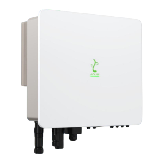
Isuna 10000~20000TO 4.3 Appearance Description 4.3.1 Appearance Description Please carefully inspect the packaging and accessories of the product before installation. PV DC input port (PV+/-) PV DC input switch Waterproof and breathable device Battery DC input port (BAT+/-) Communication module interface WiFi/4G interface Off-grid AC wiring port Grid-connected AC wiring port... - Page 15 Isuna 10000~20000TO Figure 4.1 Illustration of the appearance of the inverter...
-
Page 16: Size Description
Isuna 10000~20000TO 4.3.2 Size Description Figure 4.2 Overall size of inverter Figure 4.3 Dimensions of wall mount... -
Page 17: Installation
Isuna 10000~20000TO 5 Installation 5.1 Installation Requirements 5.1.1 Installation Environment Requirements 1) The equipment must not be installed in flammable, explosive, corrosive and other environments. 2) The installation position should be away from water pipes and cables in the wall to avoid danger during drilling. -
Page 18: Mounting Carrier Requirements
Isuna 10000~20000TO 5.1.2 Mounting Carrier Requirements 1) The installation carrier must not be flammable material and must have fire resistance. 2) Please ensure that the installation carrier is solid and reliable, and can carry the weight of the inverter. 3) When the equipment is running, it will make noise. Do not install it on the carrier with poor sound insulation, so as to avoid the noise emitted by the equipment when it is working, which will cause trouble to residents in the living area. - Page 19 Isuna 10000~20000TO...
-
Page 20: Mounting Tools
Isuna 10000~20000TO 5.2 Mounting Tools Table 5-1 List of installation tools Series Tools Description Function Percussion drill Recommended Wall drilling 8mm drill 6mm cross-head Removing, installing screwdriver screws and wiring 4mm cross-head Removing and installing screwdriver load terminal screws Removal of PV, BAT line Removal tool end terminals Wire strippers... - Page 21 Isuna 10000~20000TO Pressure welding grid, Crimping pliers load end cable Fasten the grid terminal to 6mm hex wrench the cable Check whether the cable wiring is correct, the positive and negative Multimeter battery terminals are correct and voltage, and grounding is reliable Marking pen Drilling mark Tape...
-
Page 22: Inverter Transportation
Isuna 10000~20000TO 5.3 Inverter Transportation When carrying out the transportation, turnover, and installation, you must comply with the laws, regulations and related standards of the country or region where you are located. The inverter is heavy. Please keep it balanced during handling to prevent the inverter ... - Page 23 Isuna 10000~20000TO 13mm...
-
Page 24: Electrical Connection
Isuna 10000~20000TO 6. Electrical Connection Before installation and maintenance, ensure that the AC/DC side is not powered on. The capacitors are still powered on for a period of time after the inverter is powered off. Therefore, wait at least five minutes to ensure that the capacitors are fully discharged. Three-phase off-grid inverters are used in battery energy storage photovoltaic systems. - Page 25 Isuna 10000~20000TO NOTE: 1、Recommended parameters for DC circuit breakers on the battery side: Rated voltage ≥1000V, rated current ≥63A 2、Power grid side AC circuit breaker parameters recommended: rated voltage ≥500V, rated current ≥63A 3、Back-up AC circuit breaker parameters recommended: rated voltage ≥500V, rated current ≥40A Figure 6.1 Electrical connection diagram Note: During final installation, circuit breakers for external connections to the inverter shall comply with IEC 60947-1 and IEC 60947-2 certification requirements。...
-
Page 26: External Port Wiring Instructions
Isuna 10000~20000TO 6.2 External Port Wiring Instructions Table 6-1 Cable Model and Specification Descriptions Cable Port Definition Cable type specification +: Connect Recommended to PV 6mm² positive pole Outdoor cross-sectional Multi-Core area of -: Connect Copper conductor, to PV Cable maximum negative current through... -
Page 27: Connecting The Ground Cable (Pe)
Isuna 10000~20000TO is 30A, grounding cable specifications are the same as the phase conductor Recommended 10mm² cross-sectional area of conductor, Outdoor maximum Multi-Core current through grid Copper the wire is port Cable 60A, grounding cable specifications are the same as the phase conductor 6.3 Connecting the Ground Cable (PE) Since the inverter is a transformer-free type, it is required that the positive and negative... -
Page 28: Connecting The Pv Cable And The Battery Cable
Isuna 10000~20000TO For yellow-green outdoor cables, use a wire stripper to strip the insulation layer of the ground cable to an appropriate length. Insert the wire core stripped of the insulation layer into the conductor crimping area of the OT terminal, and press it tightly with wire crimping pliers. Figure 6.2 Schematic diagram of protection grounding 6.4 Connecting the PV Cable and the Battery Cable PV series connection:... - Page 29 Isuna 10000~20000TO Before connecting the PV series to the inverter, confirm the following information. Otherwise, the inverter may be permanently damaged or fire may occur, which may cause personal and property loss. Ensure that the maximum short circuit current and maximum input voltage of each PV ...
- Page 30 Isuna 10000~20000TO Ensure that the cables are securely connected. Otherwise, the terminal may overheat and damage the device. NOTE: 1.Before crimping the PV and BAT cables, ensure that the PV knob switch is set to OFF and the battery is powered off. 2.The photovoltaic module used to connect to the inverter should meet the IEC 61730 certification of grade A standard requirements, each photovoltaic series and battery input from the external circuit breaker allowed through the maximum current should be more than or...
- Page 31 Isuna 10000~20000TO Part of the DC cable conductor is connected to the metal DC terminal and pressed by crimping pliers Insert the DC cable into the DC terminal, insert the waterproof rubber ring into the DC terminal, and tighten the nut Remove the terminal Remove Terminal After clamping, pull out the terminal...
-
Page 32: Connecting The Ac Grid-Connected Cable
Isuna 10000~20000TO 6.5 Connecting the AC Grid-Connected Cable Ensure that the AC cable matches the L1, L2, L3, N, and ground ports of the AC terminal properly. Incorrect connection may cause device damage. Ensure that the cable core is fully connected into the wiring hole of the terminal. ... -
Page 33: Connect Ac Load Cable
Isuna 10000~20000TO Install Dismantle Figure 6.4 Connecting AC grid-connected cables The maximum current allowed to pass through the circuit breaker used for the power grid should be greater than or equal to 60A. 6.6 Connect AC Load Cable... -
Page 34: Installation Of Communication Dongle
Isuna 10000~20000TO Install Dismantle Figure 6.5 Connecting AC load cables The maximum current allowed through the circuit breaker for off-grid load to the external connection should be greater than or equal to 30A. 6.7 Installation of Communication Dongle The communication collector is an external component that you need to select by yourself. - Page 35 Isuna 10000~20000TO Table 6-2 Indicators on the AGN8 WIFI Dongle state Specific meanings Alternating flashing (cycle 1500ms, each light Self test mode flashes for 500ms in sequence) Dongle is currently RUN&COM&NET Flashing together (cycle 1 second, off 900ms, on upgrading (including 100ms) Bluetooth App upgrade) Illuminate together for 5 seconds...
-
Page 36: Connecting The Communication Port
Isuna 10000~20000TO Table 6-3 Meaning of AGN9 4G Dongle indicator light state Specific meanings RUN&COM&NET The process from power Always on on to initialization Gateway initialization Flash (with an interval of 100ms) completed, flashing for 5 seconds Twice flashing (on (off) 100ms, off (on) 100ms, Slow flashing (with an twice)... - Page 37 Isuna 10000~20000TO...
- Page 38 Isuna 10000~20000TO Figure 6.7 Interface diagram Definition Function of heat pump/diesel generator multiplexed DO interface METER Electric meter communication interface BMS1 BMS1 CAN port &EMS RS485 multiplex port BMS2 BMS2 CAN port &EMS RS485 multiplex port DRMs/ diesel generator/lead-acid battery temperature sampling function multiplex interface PARA1...
-
Page 39: Bms Communication Connection
Isuna 10000~20000TO Figure 6.8 Sequence of RJ45 crystal terminals Orange Green& Blue& Brown& Orange Blue Green Brown &White White White White Table 6-5 RJ45 cable sequence colors 6.8.1 BMS Communication Connection Table 6-6 Description of BMS1 ports Color Definition Function Note Orange&... -
Page 40: Drms/Di Connection
Isuna 10000~20000TO Table 6-7 Description of BMS2 ports Color Definition Function Note Orange& RS485 differential RS485-A2-BMS White signal A2 RS485 differential Orange RS485-B2-BMS signal B2 BMS2 CAN port &EMS RS485 multiplex port Blue CANA-H2-BMS CAN high level data Blue& CANA-L2-BMS CAN low level data White Note: Communication with lithium batteries requires attention to the battery's... - Page 41 Isuna 10000~20000TO Brown NTC connection for lead acid battery: ① Cut one end of the standard network cable ② Strip the green, green&white, and blue wires at the fracture by 5mm ③ Weld it together with the NTC pin as shown in the following figure (After confirming that the welding is solid, wrap the welding place with insulation tape respectively, pay attention to avoid contact with bare metal, prevent short circuit, and affect normal use) ④...
-
Page 42: Paralleling
Isuna 10000~20000TO 6.8.3 Paralleling If multiple inverters are used, connect the terminal of the network cable to Pa1 of the first inverter, connect the other end to Pa2 of the second inverter, and so on. Table 6-10 describes the signal of the network cable. Figure 6.8 shows the sequence of the network cable connection. - Page 43 Isuna 10000~20000TO Application note: Supports a maximum of 6 three-phase off-grid inverters in parallel;; Ensure that the inverters are connected to parallel lines;; Ensure that the load power is less than the maximum parallel power.。 The length of the cable connecting the load end of the inverter to the BACK UP end of ...
- Page 44 Isuna 10000~20000TO...
-
Page 45: Inverter Operation
Isuna 10000~20000TO 7 Inverter Operation 7.1 Pre-power-on Inspection Serial Check the entry The inverter is firmly fixed to the mounting bracket on the wall. Cables are bundled according to cable routing requirements, properly distributed, and without damage. PV+/PV-, BAT+/BAT- cables are firmly connected, the polarity is correct, and the voltage is within the accessible range. - Page 46 Isuna 10000~20000TO Specific working mode: When the PV is sufficient, the PV priority for supplies power to the load, and excess power charges the battery. When the PV is insufficient, the PV and battery supply power to the load. ...
-
Page 47: Timed Charge Mode
Isuna 10000~20000TO 7.3.2 Timed Charge Mode Function: Set the charging period according to the user's own requirements. For example, when the electricity price is high during the day, the battery and photovoltaic power are used to power the load, and when the electricity price is low at night, the battery is charged with the electricity of the grid, so as to achieve the role of peak cutting and valley filling. -
Page 48: Backup Mode/Disaster Recovery Mode
Isuna 10000~20000TO Charging period: 7.3.3 Backup Mode/Disaster Recovery Mode Function: Always keep the battery fully charged to cope with sudden power grid outages or other emergencies, so that users can use the battery power to supply power to the load after an emergency occurs. -
Page 49: Operation Mode
Isuna 10000~20000TO 7.4 Operation Mode 7.4.1 Operation Mode Description Table 7-1 Inverter operating modes Series Mode Description Waiting phase after the inverter is powered on. Standby Enter the self-check state when the conditions are met. If a fault occurs, the inverter enters the fault state. Before the inverter starts, continue to self-check and initialize. - Page 50 Isuna 10000~20000TO If it is detected that the power grid does not exist or the conditions do not meet the requirements for grid connection, it enters the off-grid working state. If a fault is detected, the system enters the fault state. If the power grid conditions do not meet the grid-connection requirements and the off-grid output function is not enabled, the system enters the waiting state.
-
Page 51: Indicator Light Description
Isuna 10000~20000TO 7.4.2 Indicator Light Description The bar indicator in the middle of the device panel indicates the inverter status in red, green, and blue colors. Table 7-2 Indicator status description Indicator light Corresponding Display item Notes status status description Indicates that the inverter is currently working in a grid... - Page 52 Isuna 10000~20000TO current working status is in shutdown state, and it can be turned on and used normally after the code upgrade is completed. Indicates that the inverter is currently working in an off-grid Blue state and cannot Always on Off-grid exchange energy with the power grid.
- Page 53 Isuna 10000~20000TO Indicates that the inverter is currently in shutdown state, an Flashes System error alarm occurs on the 2s/time inverter, and the load cannot be powered...
-
Page 54: App Introduction
Isuna 10000~20000TO 8 App Introduction Users need to choose WiFi dongle or 4G dongle. ESS LINK Operation and use Please contact the manufacturer and check the ESS LINK operation and use manual. Android version: Please scan the QR code below to obtain. IOS version: Please scan the QR code below to obtain or go to the App Store search ESS LINK to download. -
Page 55: Troubleshooting And Maintenance
Isuna 10000~20000TO 9. Troubleshooting and Maintenance This section will help you determine the cause of the problem you may be experiencing. 9.1 Alarm and Processing Faults not mentioned in the following table still exist after being powered on. Contact your dealer or after-sales service center. Sequence Fault name Note... - Page 56 Isuna 10000~20000TO Check whether the PV connection mode set PV connection mode Alarm on the APP host is consistent with the actual is incorrect PV connection mode. PV1/2 power tube is Disconnect all AC and DC circuit breakers and ...
- Page 57 Isuna 10000~20000TO when the temperature of the lead-acid battery is reduced to normal temperature. Check whether the wiring sequence between the NTC and the network cable is correct. Reinsert the network cable from the communication port. Check whether the battery connection mode ...
- Page 58 Isuna 10000~20000TO connections of the inverter are correct, and whether the power grid is powered off. If the power grid voltage/frequency is not within the acceptable range, the AC connection is correct, but the alarm is repeated, please contact technical support to change the power grid overvoltage and underfrequency protection value.
- Page 59 Isuna 10000~20000TO sends a command to clear the fault. If it is confirmed that the impedance is indeed lower than the default value in a cloudy and rainy environment, reset the insulation impedance protection point. Please check whether the inverter is ...
- Page 60 Isuna 10000~20000TO close the disconnected circuit breakers after 5 minutes. If the fault persists, contact your dealer or after-sales service center. Check whether the ground cable connected to the inverter is damaged or the connection Bad earth Fault screws are not tightened, resulting in poor contact.
-
Page 61: Regular Maintenance
Isuna 10000~20000TO The DSP1/2 parameter Settings Fault are faulty Please contact your distributor or after-sales The DSP/CPLD service center to check whether the version is Fault parameters in the APP are set correctly or the incompatible. software version is upgraded Procedure The communication between the DSP... -
Page 62: Technical Parameters
Isuna 10000~20000TO 10. Technical Parameters Table 10 Technical Parameters Description Product model Isuna 10000TO Isuna 12000TO Isuna 15000TO Isuna 18000TO Isuna 20000TO Battery parameter Number of battery input channels Battery type Lithium battery/Lead-acid battery Battery voltage range 125~800V Full load battery voltage 200V-800V 240V~800V 300V~800V... - Page 63 Isuna 10000~20000TO Number of PV input channels 22500WP 27000WP 30000WP 15000WP 18000WP Maximum input power (11250WP/11250WP (13500WP/13500WP (15000WP/15000WP (7500WP/7500WP) (9000WP/9000WP) Maximum input voltage 1000V MPPT voltage range 130~960V MPPT full load voltage 250V~850V 290V~850V 350V~850V 410V~850V 450~850V range Starting voltage 130V Rated input voltage 600V...
- Page 64 Isuna 10000~20000TO Backfeed current Parallel input and output parameters Maximum grid input power 20kVA 24kVA 30kVA 36kVA 40kVA Maximum grid input current Nominal voltage 3L/N/PE,220V/380Vac,230V/400Vac Grid voltage range 184~276V Rated grid frequency 50/60Hz Nominal Grid frequency 45Hz~55Hz/55Hz~65Hz Power factor -0.8~0.8 THdI(@ Nominal power) <3% Off-grid output parameters...
- Page 65 Isuna 10000~20000TO Thdu(@ linear load) <3% On/off-grid switch-over <10ms time Efficiency European efficiency 97.70% Maximum efficiency 98.20% Maximum battery charge/discharge 97.80% efficiency Protection DC Switch Available Input reverse Available Output overvoltage, Available overcurrent, short circuit Anti-islanding Available Residual current detection Available Insulation resistance Available...
- Page 66 Isuna 10000~20000TO Surge protection level DC:II ; AC:Ⅲ Battery input reverse Available connection protection Routine parameters Weight 35kg Noise <45dB Topology No isolation Working altitude <4000m Derating Temperature >40℃ Ambient Temperature -25℃~60℃ Ambient Humidity 5%~95% Cooling method Air cooling IP Degrees IP65 Dimensions 573*509*219mm...
- Page 67 Isuna 10000~20000TO AC output terminal 5P connector interface RS485/CAN/DRED/DO/Parallel port Human-computer H5/LED/APP/WIFI/4G/Bluetooth interaction mode Scalability in Parallel Support function Standard Warranty 5 years Certification Safety regulations IEC 62109-1, IEC 62109-2, EN 62109-1, EN 62109-2,IEC62477-1 EN61000-6-1, EN61000-6-2, EN61000-6-3, EN61000-6-4,EN 62920...
Need help?
Do you have a question about the suna 10000TO and is the answer not in the manual?
Questions and answers