
Related Manuals for Sinexcel PWS2-30K-NA


Summary of Contents for Sinexcel PWS2-30K-NA
- Page 1 PWS2-30K-NA Energy Storage Inverter User's Manual Shenzhen Sinexcel Electric Co., Ltd.
- Page 2 Filed in: March 15, 2017 Applicable to: PWS2-30K-NA Shenzhen Sinexcel Electric Co., Ltd. (“Sinexcel”) provides its customers with all-around technical support. Users can contact local Sinexcel office or customer service center or directly contact Sinexcel Headquarters. Shenzhen Sinexcel Electric Co., Ltd.
-
Page 3: Table Of Contents
CONTENT CHAPTER 1 OVERVIEW ____________________________________________________ - 1 - __________________________________________________________ - 1 - ODEL DEFINITION _________________________________________________________ - 1 - CON INTERPRETATION 1.2.1 Icons in the manual _____________________________________________________ - 1 - 1.2.2 Inverter prompt icons ____________________________________________________ - 2 - ________________________________________________________ - 2 - AFETY INSTRUCTIONS 1.3.1 Safety instructions for mechanical installation ________________________________ - 3 -... - Page 4 CHAPTER 4 DEBUG AND OPERATION ________________________________________ - 36 - _____________________________________________________ - 36 - TARTUP AND SHUTDOWN 4.1.1 Check before startup____________________________________________________ - 36 - 4.1.2 Startup steps __________________________________________________________ - 36 - 4.1.3 Shutdown steps ________________________________________________________ - 36 - _________________________________________________________ - 37 - OWER REGULATION CHAPTER 5 HMI AND OPERATIONS _________________________________________ - 38 - ______________________________________________________________ - 38 -...
-
Page 5: Chapter 1 Overview
Chapter 1 Overview 1.1 Model definition The model definition of PWS2-30K-NA energy storage inverter is shown in Fig. 1-1: Fig. 1-1 Model definition 1.2 Icon interpretation This user’s manual is about installation and use of Sinexcel PWS2-30kW energy storage inverter. -
Page 6: Inverter Prompt Icons
1.3 Safety instructions PWS2-30K-NA energy storage inverter is designed and tested in strict accordance with relevant international safety standards. Its installation, trial operation, operation and maintenance should comply with safe operation specifications of electrical and electronic equipment. -
Page 7: Safety Instructions For Mechanical Installation
electrical and electronic equipment; be familiar with relevant safety specification of electric system. Professionals who meet the above conditions can: (1) Install the inverter onto the wall; (2) Setup energy storage system as per customer’s requirement; (3) Conduct trial operation of energy storage system; (4) Operate, debug and maintain energy storage system. -
Page 8: Safety Instructions For Inverter Operation
All electrical installations should meet national/regional electrical standards; Grid-tied operation can be conducted after permission is obtained from local national/regional electric power department. CAUTION Before power-on, please ensure that it is reliably grounded and the grounding meets local electrical standards. 1.3.3 Safety instructions for inverter operation Any contact with copper bar, uncovered contact spot or terminal inside the device that is connected to the loop of power grid might result in... -
Page 9: Safety Instructions For Maintenance And Replacement
1.3.4 Safety instructions for maintenance and replacement Improper equipment maintenance and operation might cause personal injury or equipment damage. Before any operation, users should strictly abide by the following steps: Disconnect the AC isolation switch between the power grid and the inverter, and then turn off DC breaker of the battery box. -
Page 10: Others
1.3.5 Others Safety signs, warning label and nameplate on the inverter: Must be clearly visible; WARNING Should not be removed or covered. 1.4 Precautions 1.4.1 Personnel requirements Energy storage inverter must be debugged and maintained by the engineers designated by the manufacturer or its agent. Otherwise, it might endanger personal safety and result in device fault. -
Page 11: Chapter 2 Introduction To Energy Storage System
Chapter 2 Introduction to energy storage system 2.1 System application As shown in Fig. 2-1, the energy storage system set up by PWS2-30K-NA is composed of battery (pack), energy storage inverter, intelligent power distribution unit, EMS and BMS. Battery pack is connected to energy storage inverter. Energy storage inverter is connected with the load and power grid through intelligent power distribution unit. -
Page 12: Adaptive Power Grid Type
PORT. THE DEVICES CAN BE CONNECTED TO THE POWER GRID IN PARALLEL ON AC PORT. THE DC PORT OF TWO OR MORE ENERGY STORAGE INVERTERS SHOULD NOT BE PARALLELED ON ONE SAME BATTERY PACK/MODULE. 2.2 Overall dimension Overall dimension of PWS2-30K-NA is shown in Fig. 2-3. - 8 -... -
Page 13: Appearance
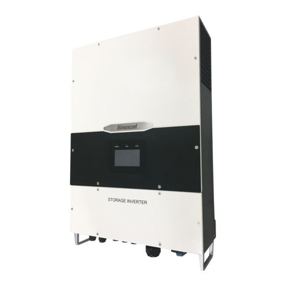
Fig. 2-3 Overall dimension of PWS2-30K-NA (unit: mm) 2.3 Appearance The appearance of PWS2-30K-NA is shown in Fig. 2-4. Fig. 2-4 Appearance of front side of PWS2-30K-NA Name Description DC port To connect power cables to the battery cabinet Communication interfaces... -
Page 14: Technical Parameters
Upper panel Case cover Air outlet Ventilation duct exit for heat dissipation Fig. 2-5 Appearance of back side of PWS2-30K-NA 2.4 Technical parameters Technical parameters of PWS2-30K-NA energy storage inverter: Table 2-1 Technical parameters DC port DC voltage range 200V~750V(350~750V Full Load) Max. - Page 15 DC voltage ≤1% accuracy Charge and 3-phase charging (constant powerconstant voltagetrickle discharge mode current); constant current discharging, constant power discharging AC port (grid-tied mode) Rated output 30kW power Rated grid voltage 480V Grid voltage range -12%~+10% Rated grid 60Hz frequency Range of grid ±2.5Hz frequency...
- Page 16 factor 0 leading~0 lagging (actual) AC port (off-grid mode) Off-grid AC 480V voltage Off-grid AC ±5% voltage range Off-grid AC 60Hz frequency Off-grid output ≤1% voltage stabilizing accuracy Off-grid output ±0.1Hz frequency accuracy ≤1% (linear load) Off-grid THDu ≤5% (nonlinear load) 105%~115% 10min Output overload 115%~125% 1min...
- Page 17 Installation mode Wall-mounted Wiring mode 3-phase +N+PE Isolation mode Non-isolated Cooling mode Fan cooling Standby self- power <20W consumption ≤60dB Noise Temperature -20℃~60℃ (de-rating in case of exceeding 45° C) range Enclosure CLASS I/NEMA1(IP32) Altitude 4,000m (de-rating in case of exceeding 2,000m) Humidity 0~95% Dimension...
-
Page 18: Technical Specification
2.5.1 Principle description There are three operation modes: grid-tied discharging, charging and off-grid discharging. When the battery voltage connected to PWS2-30K-NA is within the preset normal voltage range, the inverter can operate under grid-tied discharging, charging and off-grid discharging. If the inverter is in discharging state, the DC power supply of the battery can be inverted into 3-phase AC power supply. - Page 19 record are displayed on the LCD screen. Communication function: Standard RS-485 interface can be connected with monitoring device such as EMS. Standard Ethernet interface is used to communicate with upper computer to realize such functions as remote control and remote software upgrading. Reactive power configuration: Regulate the reactive power of the storage system.
-
Page 20: De-Rating
Grid voltage monitoring Grid frequency monitoring Anti-islanding protection Monitoring of AC output current and DC component Battery overcharge protection Battery over-discharge protection 2.5.3 De-rating The de-rating of inverter is to avoid inverter overload or restrain potential faults. The inverter might conduct de-rating operation in the following operating conditions: Internal over-temperature (including... - Page 21 Fig.2-6 Grid under-voltage de-rating Battery under-voltage de-rating If the battery voltage is too low, the inverter will limit the battery discharge current to a specified range through de-rating. The de-rating of battery under-voltage will be activated when the battery voltage reaches 350V. The curvilinear relationship for battery voltage de- rating is as follows: Working Zone...
- Page 22 Fig.2-8 Grid over-voltage de-rating Grid over-frequency de-rating If the grid frequency is too high, the inverter will limit the active power to a specified range through de-rating. The de-rating of grid over-frequency will be activated when grid frequency reaches f1(f1 could be set by RS485 or Ethernet). The curvilinear relationship for grid frequency de-rating is as follows: Fig.2-9 Grid over-frequency de-rating - 18 -...
-
Page 23: Chapter 3 Equipment Transport, Storage And Installation
Chapter 3 Equipment transport, storage and installation 3.1 Transport and storage During transport and storage of inverter cabinet, pay attention to the packing label on enclosure. Transport and storage should meet the following requirements: Don’t dismantle external package of the inverter. Ensure there is no corrosive gas nearby. -
Page 24: Installation Flow
3.2 Installation flow Start Unpack & Inspect Read manual Install now? Store Select installation location Transport Install Electrical connection Inspect before operation Trial operation Operates Debug Nomarlly? Fig. 3-1 Flow chart for installation - 20 -... -
Page 25: Open-Case Inspection
3.3 Open-case inspection 3.3.1 Overview Before delivery, each inverter is strictly checked and tested. To prevent any damage during transport, the case needs to be opened and checked before installation of energy storage inverter. The following should be checked: Check whether the items in the packing list are consistent with the real objects. Check whether the data (such as product model, rated capacity and voltage) on the product nameplate is consistent with purchase contract. -
Page 26: Model Check And Preparation
To fix the latch panel to the Expansion bolt (M12 × preinstalled position Including QC certificate, packing Documents pack list, ex-factory test report To protect the RJ45 connector and RJ45 connector cap cable connected Ф5.5-5 Ring terminal To fix ground wire To fix the cable in AC to the wiring Ф6 cord end terminal terminal... -
Page 27: Installation Requirements
Fig. 3-3 Nameplate * The above picture is only for reference. Please refer to the real object. (1) Product model and serial number (2) Technical parameters of inverter (3) Precaution and warning label (4) Manufacturer 3.5 Installation requirements 3.5.1 Environment requirements The inverter is designed for indoor use. - Page 28 It is recommended that the inverter should be installed at certain level in height so as to easy operation and follow-up maintenance. PWS2-30K-NA inverter is cooled by fan. The air flow direction is bottom inlet and side outlet. - 24 -...
-
Page 29: Installation
During installation, there should be sufficient space around the inverter so as to ensure enough installation and heat dissipation space, as shown in Fig. 3-6. >400mm >700mm >700mm >400mm Fig. 3-6 Installation space of energy storage inverter 3.6 Installation 3.6.1 Inverter transport Take the case out of the external package and transport it horizontally to the designated installation position. - Page 30 in Fig. 3-8. To regulate the holes and mark them with horizontal ruler. Fig. 3-8 Confirmation of drilling position Step 2: Use a percussion drill to punch holes and install the expansion bolts. The operation process is shown as follows: (1) Select a Ф10mm drill and use a percussion drill to punch the holes at the marked positions perpendicular to the wall.
- Page 31 Fig. 3-10 Fix latch panel To prevent the dust from entering the respiratory tract or the eyes during drilling, operator should wear goggles and dustproof mask. Use a vacuum cleaner to clear the dust inside and outside the holes, measure the layout of holes. Reposition and drill holes if there are any CAUTION errors.
-
Page 32: Electrical Connection
Fig. 3-12. Fig. 3-12 Hanging the inverter 3.7 Electrical connection PWS2-30K-NA electrical wiring should strictly following the following requirements. Please read the following carefully. Before electrical connection, please ensure that all switches of energy storage system are in “OFF” state. Otherwise, the high voltage of the inverter might cause an electric shock risk. - Page 33 For detailed information, consult WARNING qualified technical service personnel. PWS2-30K-NA does not include GFDI function, and the system needs to configure BMS containing DC GFDI function. 3.7.2 Introduction to bottom of PCS Fig. 3-14 Terminals...
- Page 34 Before connection of AC, DC and communication cables, the grounding wire should be connected first. It is recommended that the inverter should be grounded locally. For multiple PWS2-30K-NA parallel connection system, the grounding CAUTION points of all inverters should be connected with each other so as to ensure equal potential connection of grounding wires.
- Page 35 3.7.5 DC wiring Step 1: Use a multi-meter to measure the voltage of battery, and ensure that the voltage is within input voltage range of energy storage inverter. Step 2: Turn off the DC breaker. Wiring operation can be conducted after using a multi- meter to measure and confirm that there is no voltage between positive and negative poles of DC input.
- Page 36 PWS2-30K-NA has three different communication interfaces: Ethernet, RS-485 and CAN. (1) Ethernet cable connection PWS2-30K-NA can be directly networked through Ethernet and connected to PC for communication. Through networking, users can remote dispatch energy, monitor operation state, and set parameters with background software in PC. The definition of RJ45 connector pin is shown in Fig.
-
Page 37: Check After Installation
control and protection of energy storage system. RS-485 is connected through RJ45 connector. The definition of the pin of RJ45 connector is shown in Fig. 3-19. The connection steps are the same as Ethernet cable. Fig. 3-19 RS-485 wiring The wiring making of RS-485 is the same as Ethernet cable. RJ45 terminal should be inserted into RS-485 port and cap shall be locked. -
Page 38: Electric And Communication Check
(4) Confirm that the communication cables of Ethernet and RS-485 have been connected correctly without open circuit and short circuit. (5) Confirm that the caps of Ethernet, RS-485, CAN and power cable have been screwed 3.8.2 Electric and communication check PWS2-30K-NA DC Breaker AC Switch AC Breaker... - Page 39 Fig. 3-22 Bottom cover installation - 35 -...
-
Page 40: Chapter 4 Debug And Operation
Chapter 4 Debug and operation 4.1 Startup and shutdown Startup steps can be conducted after energy storage inverter is installed and debugged by engineers, with the power switch closed. 4.1.1 Check before startup Before startup, check the device according to the following steps: (1) Visually inspect and ensure that there is no damage outside the module, and DC breaker D1 and AC breakers S2 and D3 are in “OFF”... -
Page 41: Power Regulation
(1) Click Control in the interface of main menu of LCD touch screen, and click the round button OFF. (2) Click Home to confirm whether the inverter is in standby state. (3) Turn off AC isolator S2 and AC breaker D3. (4) Turn off DC breaker D1 of battery pack. -
Page 42: Chapter 5 Hmi And Operations
Chapter 5 HMI and operations 5.1 Description This section introduces HMI (Human-Machine Interface) content and settable parameters. Relevant settings can be conducted via HMI. The HMI can display real time warning information, provide historical warning records for user’s query and offer a reliable basis for fault diagnosis. Through HMI, users can conduct various operations, quickly browse input, output, operation parameters and waveform displaying and timely obtain current energy storage inverter state and warning information. -
Page 43: Home Page
5.3 Home page After HMI initialization, it enters Home page, as shown in Fig. 5-3. Users can review system AC and DC voltage, AC and DC current, system charging and discharging and operation state. In this page, the arrow direction for power grid, inverter and battery connecting cable is a reference direction of electric energy flowing. -
Page 44: Battery Information
and > under the interface to turn page up or down, click to return the main menu. AC information is shown in Table 5-1. Table 5-1 AC information Item Identifier Description Unit Uab, Line voltage of AC output port of Voltage UbcandUca inverter... -
Page 45: Graph Display
inverter Charging quantity CHGD Accumulated charging quantity of battery kW*h Accumulated discharging quantity of Discharging quantity DCHGD kW*h battery ℃ Temperature DC power module temperature of inverter Fig. 5-6 DC information 5.4.3 Graph display Click Graph in the left side to enter the graph display. This interface can display the curve for charging and discharging power of inverter in current day. -
Page 46: Control Parameter
Fig. 5-8 Warnings interface Click Historical Warnings to enter the historical warning interface. This interface includes three columns: “number”, “message” and “time end of warning”. Click < and > under the interface to turn page up or down, click to return the main menu, as shown in Fig. 5-9. Fig. - Page 47 Click > under the interface to turn page up to enter the inverter grid-tied and off-grid control interface. PWS2-30K-NA energy storage inverter can operate in grid-tied mode and off- grid mode. During grid-tied operation, close the isolator S2 in AC and the breaker D3 (the breaker between the inverter and the power grid.), and set the energy storage inverter in...
-
Page 48: Settings
range± 1Hz Regulate the active Active power power of AC in grid-tied Active Power regulation mode. Regulated range ± 30kW Grid-tied mode Regulate the reactive Reactive power Reactive power of AC in grid-tied regulation Power mode. Regulated range ± 30kVar When the dispatched apparent power exceeds 30kVA, the output of active power will be restricted by reactive power, and the system will give priority to reactive output. - Page 49 Fig. 5-14 Battery parameters setting Table 5-4 Content of battery parameters setting Item Identifier Description Trickle Float Charging Set as per to battery manufacturer's charging Voltage recommendation. voltage Constant voltage Equal Charging Set as per to battery manufacturer's charging Voltage recommendation.
-
Page 50: Hmi Parameters
Table 5-5. Fig. 5-15 HMI parameter setting Table 5-2 Content of HMI parameters setting Item Identifier Description Internet protocol address for PWS2-30K-NA in IP address IP Address networking Subnet mask Subnet Mask Default: 255.255.255.0... -
Page 51: Debug Interface
Click Debug to enter debugging interface, and click < and > under the interface to turn page down, and click to return the main menu. This debugging interface is used by Sinexcel electrical maintenance engineer when checking machine operation state or fault. Users cannot conduct any operation. Any loss arising from customers’ modifying the WARNING parameters in this interface will be undertaken by customers. - Page 52 return the main menu. This interface includes inverter serial number, MAC address, software build number, grid status and the rated power of the inverter. Fig. 5-16 Inverter information interface - 48 -...
-
Page 53: Chapter 6 Communication Mode
6.1.1 RS-485 interface RS-485 interface is reserved at the bottom of PWS2-30K-NA and used to communicate with EMS. As an energy dispatching unit for energy storage system, EMS accepts remote dispatching, receives BMS information and realizes control and protection of automatic charging and discharging of energy storage system. -
Page 54: Bms Communication
Fig. 6-2 Inverter connecting with EMS through Ethernet 6.2 BMS communication PWS2-30K-NA supports communication with BMS. It can obtain and detect basic state and protection information from BMS, close the energy storage inverter according to the protection state of storage battery fault and improve the safety of battery pack. RS-485 is adopted for communication between energy storage inverter and BMS, as shown in the following diagram. - Page 55 energy storage inverters. This has provided great convenience for detecting and controlling the operation of energy storage inverters. The overall structure diagram for system networking is shown in Fig. 6-4. Remote Dispatching Center Ethernet Ethernet Ethernet Switch Energy Storage Energy Storage Inverter Inverter Fig.
-
Page 56: Chapter 7 Maintenance
Chapter 7 Maintenance 7.1 Operation environment requirements Temperature: -20~60℃ Humidity: 0~95% (non-condensing) Max. elevation: 4,000m It is recommended that the operating temperature should be maintained between -20~45℃ so as to ensure the best performance of the convert. If the temperature is too high or low, it will shorten the service life of inverter. -
Page 57: Appendixes
Appendixes Appendix I: Fault list of energy storage inverter Table 1 presents the visible fault types of energy storage inverter. From this table, users can simply and quickly identify the system faults based on the fault types displayed on HMI. Table 1 Fault list Fault codes Fault type... - Page 58 environment 15V power F 15V power fault 15V power voltage is too low. DC bus Ubus O/V The DC bus voltage in the inverter is too high. overvoltage DC bus under- Ubus U/V During normal operation, DC bus voltage is too low. voltage Ubus Imbalance of...
- Page 59 DC battery has overcurrent. Load needs to be DC O/A DC overcurrent reduced. Otherwise, shutdown will occur due to overload. Discharging DC voltage is lower than threshold, charge the DCH disabled disabled battery, or manually clear the fault - 55 -...
- Page 60 As for the products requiring repair, users should give reasonable and sufficient time. We apologize for any inconvenience caused to you. (3) In case of any of the following circumstances, Sinexcel will not offer any quality assurance: ...
- Page 61 Installation records Installation records - 57 -...
- Page 62 Feedback Feedback - 58 -...
Need help?
Do you have a question about the PWS2-30K-NA and is the answer not in the manual?
Questions and answers