
Related Manuals for Sinexcel Isuna 3000SO


Summary of Contents for Sinexcel Isuna 3000SO
- Page 1 Single phase LV Off-grid Inverter Isuna 3000SO-6000SO Shenzhen Sinexcel Isuna Energy Technology Co.,LTD.
-
Page 2: Table Of Contents
Isuna 3000-6000SO Catalogue 1.Overview ....................... 3 1.1 Scope of Application ................. 3 1.2 Intended Users ................. 3 1.3 Symbols Used in This Manual ............3 2. Safety Precautions ..................4 2.1 Operation Safety ................4 2.2 PV String Safety ................5 2.3 Battery Safety ................... - Page 3 Isuna 3000-6000SO 6.1 Electrical System Connection Diagram .......... 18 6.2 External Port Wiring Instructions ............ 20 6.3 Connecting the Ground Cable (PE) ..........21 6.4 Connecting the PV Cable ............... 22 6.5 Connecting the AC and Battery Cable ..........23 6.6 Installation of WIFI antenna ............
-
Page 4: Overview
1.1 Scope of Application This document applies to the inverters of the following models: Model Rated output power Rated output voltage Isuna 3000SO 3000W Isuna 4000SO 4000W 220V,L/N/PE Isuna 5000SO... -
Page 5: Safety Precautions
Isuna 3000-6000SO avoided. Indicates a hazard with a low level of potential that, if not avoided, could result in moderate or minor injury. Indicates a potentially hazardous situation that, if not avoided, may cause equipment failure or property damage. 2. Safety Precautions The safety precautions contained in this document must be followed when operating the inverter. -
Page 6: Pv String Safety
Isuna 3000-6000SO 2.2 PV String Safety Use the DC wiring terminal delivered with the chassis to connect the DC cables of the inverter. Use of other types of DC terminals may cause serious consequences. Therefore, the manufacturer is not responsible for the damage to the device. Ensure that the assembly frame is properly grounded to the support system. -
Page 7: Inverter Safety
Isuna 3000-6000SO 2.4 Inverter Safety Ensure that the voltage and frequency of the grid-connected access point comply with the inverter grid-connected specifications. A protection device, such as a circuit breaker or fuse, is recommended for the AC side of ... -
Page 8: Equipment Inspection And Storage
Isuna 3000-6000SO It indicates the High voltage exists during inverter operation. danger of high If you need to operate the inverter, please voltage. make sure the inverter is disconnected. It indicates to be careful of The temperature of inverter housing is high high during operation, so do not touch it, otherwise temperature... - Page 9 Isuna 3000-6000SO Picture Description Quantity Inverter Bubble level 3mm hex wrench Parallel communication line BMS communication line Grounding screw M5*10 Expansion anchor bolts M8*80...
-
Page 10: Equipment Storage
Isuna 3000-6000SO User Manual 2PCS Warranty Card Parallel communication line 3.3 Equipment Storage If the inverter is not put into use immediately, store it according to the following requirements: Ensure that the outer packing case is not removed and the desiccant is not lost. ... -
Page 11: Application Scenario
Isuna 3000-6000SO 4.2 Application Scenario The photovoltaic system is not suitable for devices that rely on stable power supply, such as life-sustaining medical devices. Ensure that no personal injury is caused when the system is powered off. Do not use a load with a high starting current in the photovoltaic system. Otherwise, the ... -
Page 12: Appearance Description
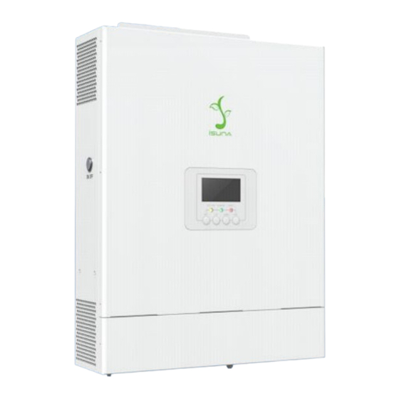
Isuna 3000-6000SO 4.3 Appearance Description 4.3.1 Appearance Description Please carefully inspect the packaging and accessories of the product before installation. Figure 4.1 Appearance of the inverter Table 4-1 Appearance of the inverter Multifunctional communication interface PV DC input port (PV+/-) WiFi antenna Overload reset button Battery DC input port (BAT+/-) -
Page 13: Size Description
Isuna 3000-6000SO 4.3.2 Size Description Figure 4.2 Inverter dimensions... -
Page 14: Installation
Isuna 3000-6000SO 5 Installation 5.1 Installation Requirements 5.1.1 Installation Environment Requirements 1) The equipment must not be installed in flammable, explosive, corrosive and other environments. 2) The installation position should be away from water pipes and cables in the wall to avoid danger during drilling. -
Page 15: Mounting Tools
Isuna 3000-6000SO 2) Please ensure that the installation carrier is solid and reliable, and can carry the weight of the inverter. 3) When the equipment is running, it will make noise. Do not install it on the carrier with poor sound insulation, so as to avoid the noise emitted by the equipment when it is working, which will cause trouble to residents in the living area. -
Page 16: Inverter Transportation
Isuna 3000-6000SO Marking pen Drilling mark Tape Measurement distance Wear when setting up Protective gloves the inverter Goggles Wear when drilling holes Dust mask Wear when drilling holes 5.3 Inverter Transportation Remove the inverter from the outer packaging and carry it horizontally to the designated mounting position. -
Page 17: Wall Mounted
Isuna 3000-6000SO When carrying out the transportation, turnover, and installation, you must comply with the laws, regulations and related standards of the country or region where you are located. The inverter is heavy. Please keep it balanced during handling to prevent the inverter ... - Page 18 Isuna 3000-6000SO Figure 5.1 Illustrative diagram for installation of wall hangings...
-
Page 19: Electrical Connection
Isuna 3000-6000SO 6. Electrical Connection Before installation and maintenance, ensure that the AC/DC side is not powered on. The capacitors are still powered on for a period of time after the inverter is powered off. Therefore, wait at least five minutes to ensure that the capacitors are fully discharged. single -phase hybrid inverters are used in battery energy storage photovoltaic systems. - Page 20 Isuna 3000-6000SO Recommended circuit breaker specifications: DC circuit breaker 120A; AC circuit breaker: 40A (of which the grid-side AC circuit breaker needs to be decided according to the actual load power used and local regulations). Note: During final installation, circuit breakers for external connections to the inverter shall comply with IEC 60947-1 and IEC 60947-2 certification requirements.
-
Page 21: External Port Wiring Instructions
Isuna 3000-6000SO 6.2 External Port Wiring Instructions Select the cable size applicable to the parameters of the inverter according to its model. Table 6-1 Cable Model and Specification Descriptions Port Definition Cable type Cable specification +: Connect to battery positive pole Outdoor Wire cross sectional... -
Page 22: Connecting The Ground Cable (Pe)
Isuna 3000-6000SO Outdoor Wire cross sectional grid Multi-Core area: 6mm²~10mm² port Copper Cable 6.3 Connecting the Ground Cable (PE) Since the inverter is a transformer-free type, it is required that the positive and negative electrodes of the photovoltaic array cannot be grounded, otherwise the inverter will fail. In the photovoltaic power generation system, all non-current-carrying metal components (such as brackets, distribution cabinet enclosures, inverter enclosures, etc.) should be connected to the ground. -
Page 23: Connecting The Pv Cable
Isuna 3000-6000SO 6.4 Connecting the PV Cable Do not connect the same PV series to multiple inverters. Otherwise, the inverters may be damaged. Before connecting the PV series to the inverter, confirm the following information. Otherwise, the inverter may be permanently damaged or fire may occur, which may cause personal and property loss. -
Page 24: Connecting The Ac And Battery Cable
Isuna 3000-6000SO 6.5 Connecting the AC and Battery Cable Battery cable connection: A battery short circuit may cause personal injury. However, a short circuit may release a large amount of energy, which may cause fire. Before connecting the battery cable, ensure that the inverter and battery are powered ... -
Page 25: Installation Of Wifi Antenna
Isuna 3000-6000SO and damage the device. Step 1: According to the cable model and specification in Table 6-1, select the appropriate cable type and specification, and strip the cable insulation layer; Step 2: Insert the wire core stripped of the insulation layer into the conductor crimping area of the copper post terminal, and press it tightly with M3 hex socket screws with a locking torque of 6.6kgf·cm. -
Page 26: Connecting The Communication Port
Isuna 3000-6000SO 6.7 Connecting the Communication Port Multifunctional communication port, including meter communication, BMS communication, DRMS, parallel communication and external dry contact signal. Figure 6.3 Interface diagram The communication cable RJ45 socket pinout sequence is shown in Figure 6.8: Figure 6.4 RJ45Sequence of RJ45 crystal terminals Orange Green&... -
Page 27: Bms/Can/Rs485Communication Connection
Isuna 3000-6000SO 6.7.1 BMS/CAN/RS485Communication Connection Table 6-5 Description of BMS/CAN/RS485 ports Definition Fuction Note TEMP_BAT TEMP_BAT ① Communication with lithium batteries requires attention to the communication port order and pin CAN_A_H CANH data definition of the battery; CAN_A_L CANL data ②... -
Page 28: Paralleling
Isuna 3000-6000SO When using the lead battery, insert the completed NTC crystal head into the DRMS interface, and stick the NTC outside the lead battery. ②Do not use NTC connection If the temperature sampling function is not needed when using the lead battery, users need to access a 100KΩ... - Page 29 Isuna 3000-6000SO Three parallel inverter wiring method: Connect GRID-L of each inverter together to the L wire of the grid side; connect GRID-N of each inverter together to the N wire of the grid side; connect PE of the grid side of each inverter together to the PE wire of the grid side.
- Page 30 Isuna 3000-6000SO The standard wiring for parallel operation is shown below.
-
Page 31: Inverter Operation
Isuna 3000-6000SO 7. Inverter Operation 7.1 Pre-power-on Inspection Serial Check the entry The inverter is firmly fixed to the mounting bracket on the wall. Cables are bundled according to cable routing requirements, properly distributed, and without damage. PV+/PV-, BAT+/BAT- cables are firmly connected, the polarity is correct, and the voltage is within the accessible range. - Page 32 Isuna 3000-6000SO Give priority to the use of photovoltaic and battery energy, as far as possible not to use the energy of the grid. Specific working mode: When the PV is sufficient, the PV priority for supplies power to the load, and excess ...
-
Page 33: Timed Charge Mode
Isuna 3000-6000SO supplies power to the load. If the PV is insufficient and the battery SOC is less than the minimum SOC, then the PV and the grid supply power to the load and the battery standby. If the PV is not working and the battery SOC is less than the minimum SOC, the grid ... - Page 34 Isuna 3000-6000SO When PV is sufficient, PV supplies power to loads and battery. When the PV is not sufficient, the PV and the grid supply power to the loads and battery. When the PV is not working, the grid supplies power to the load and battery. ...
-
Page 35: Backup Mode/Disaster Recovery Mode
Isuna 3000-6000SO 7.3.3 Backup mode/disaster recovery mode Function: According to the user's needs, the battery can be set up for power reserve. User’s can charge the battery fully in advance for use by the load in case of a power outage. Battery charging power in this mode is 5kw by default. -
Page 36: Pv Priority Charging Mode
Isuna 3000-6000SO 7.3.4 PV priority charging mode Function: The PV energy charges the battery priority according to the user's needs. Specific working mode: When PV is sufficient, PV supplies power to loads and battery. When the PV is insufficient, the PV supplies power to the battery and the grid supplies ... -
Page 37: Operating Mode
Isuna 3000-6000SO When the PV is not working, the grid supplies power to the load and the battery standby. 7.4 Operating mode Table 7-1 Explanation of Inverter Operation Modes Operating Description mode Waiting phase after the inverter is powered on. ... -
Page 38: System Testing Introduction
Isuna 3000-6000SO grid connection requirements and the off grid output function is not enabled, it will enter a waiting state. If the grid conditions meet the grid connection requirements and the grid connection function is enabled after switching off the grid, the system will enter the grid connection state. - Page 39 Isuna 3000-6000SO PV voltage 1 PV power 1 PV voltage 2 PV power 2 Active power of phase A of Load voltage frequency the grid Grid voltage frequency Load phase A current Power grid phase A voltage Load phase A voltage Load A looks at each other in Reservation power...
-
Page 40: Description Of Display And Control System
Isuna 3000-6000SO Discharge cut-off Set range: 42V default voltage 38V~44V Set range: 0,1 Special function default 1 0 self-use mode 1 Timed Charge Mode Set range: 0,1,3,5 3 Backup Work mode mode/disaster default 0 recovery mode 5 PV priority charging mode 8.2 Description of display and control system LCD display control system includes LCD display, keys and indicators, schematic diagram and physical diagram as shown in the following figure. - Page 41 Isuna 3000-6000SO The following figure shows the system parameter interface. Battery voltage 1---- Battery power 1 Display diagram Battery temperature ---- load power display diagram...
- Page 42 Isuna 3000-6000SO PV voltage 1---- photovoltaic power 1 PV voltage 2---- photovoltaic power 2 Grid A phase active power - load voltage frequency display diagram...
- Page 43 Isuna 3000-6000SO Grid Voltage Frequency - Load A Phase Current RMS Display Diagrams Grid Phase A Voltage - Load Phase A Voltage Display Diagram Reserve - Load A Phase Apparent Power Display Diagrams...
-
Page 44: Set System Parameters
Isuna 3000-6000SO Battery 1 Running status -- Model input frequency level display diagram Reserve - Device Address Display Diagrams 8.3.1 Set system parameters Step 1: Press the SET to enter the setting item, and the setting icon appears in the middle. - Page 45 Isuna 3000-6000SO Maximum charging current setting display diagram The maximum charging current setting is successfully displayed Maximum discharge current setting display diagram...
- Page 46 Isuna 3000-6000SO Maximum Discharge Current Setting Successful Display Diagram Battery type Settings display diagram Battery Type Setting Successful Display Diagram...
- Page 47 Isuna 3000-6000SO Lead battery float voltage setting display diagram Lead battery float voltage setting successful diagram Lead battery average charging voltage setting display diagram...
- Page 48 Isuna 3000-6000SO Lead battery average charging voltage setting success diagram Lead battery average charging enable setting display diagram...
- Page 49 Isuna 3000-6000SO Lead battery average charging enable setting success display diagram Battery 1 Capacity Setting Display Diagram Battery 1 Capacity Setting Successful Display...
-
Page 50: Led Indicator Status
Isuna 3000-6000SO Lead battery discharge under voltage setting display diagram Lead battery discharge under voltage setting success display diagram Note: After the system is successfully set, press the leftmost button to exit the setting screen. In this case, the screen icon is the same as that on the setting screen. 8.4 LED indicator status Note:Input and output relative to product. - Page 51 Isuna 3000-6000SO operates without batteries Grid-connected Always The grid-connected BAT -BAT operates without PV Grid-connected Always All three -BAT/PV Always Off-grid -PV No such condition Always Off-grid state BAT runs without Off-grid -BAT Always Off- grid state BAT runs Off- grid -BAT/PV without PV Alarm (no Slow...
- Page 52 Isuna 3000-6000SO Zero line anomaly Recoverable fault Ambient temperature is too high Recoverable fault Heat sink temperature is too Recoverable fault high Insulation fault Unrecoverable fault Leakage protection failure Unrecoverable fault Auxiliary power failure Recoverable fault Fan error Recoverable fault Model capacity fault Recoverable fault The surge arrester is abnormal...
- Page 53 Isuna 3000-6000SO locks DC bus undervoltage Recoverable fault DC bus voltage imbalance Recoverable fault The PV 1 power tube is faulty Recoverable fault The PV 2 power tube is faulty Recoverable fault Battery 1 power tube is faulty Recoverable fault Battery 2 power tube is faulty Recoverable fault The inverter power tube is faulty...
- Page 54 Isuna 3000-6000SO The CPLD communication is Recoverable fault faulty DSP communication failure Recoverable fault Output voltage direct current Recoverable fault exceeds the limit Direct output current exceeds Recoverable fault the limit Relay self-test failed Unrecoverable fault Inverter exception Recoverable fault Imperfect earth Recoverable fault PV 1 Soft start fails...
- Page 55 Isuna 3000-6000SO Several DC converter cavity overcurrent Unrecoverable fault locks PV 1 reverse connection Recoverable fault PV 2 reverse connection Recoverable fault Battery 1 is low Recoverable fault Battery 2 is low Recoverable fault Lithium battery 1 Do not charge Recoverable fault Lithium battery 1 Do not Recoverable fault...
- Page 56 Isuna 3000-6000SO Inverter relay short circuit Recoverable fault The PV access mode is Give an alarm incorrect The parallel module is missing Recoverable fault The parallel module number is Recoverable fault repeated Parameters of parallel modules Recoverable fault conflict Reserved 4 Reserved 5 Inverter seal pulse Recoverable fault...
-
Page 57: App Introduce
Isuna 3000-6000SO 9.App introduce Users need to choose between a WiFi dongle or a 4G dongle when using the app. ESS LINK: Please contact the manufacturer for operation and use, and refer to the ESS LINK operation and user manual. Android:Please scan the QR code below to obtain it. -
Page 58: Troubleshooting And Maintenance
Isuna 3000-6000SO 10.Troubleshooting and Maintenance This section will help users identify the possible causes of malfunction issues. 10.1 Alarm and solution Table 10-1Alarm Information List and Solutions Error Solution Please ensure that the inverter is installed in a High ambient place without direct sunlight. - Page 59 Isuna 3000-6000SO voltage automatically cleared or a fault clearing command will be sent. Battery 1 discharge termination Please check whether the connection of PV1 is correct or whether the voltage is abnormal. Once PV1 not connected confirmed it is correct, the alarm will be automatically cleared or a fault clearing command will be sent.
- Page 60 Isuna 3000-6000SO after-sales service center for help. Inverter overload Inverter overload Please check whether the inverter is working in timeout the overload state. Once confirmed that it is overload timeout normal, the alarm will be automatically cleared PV1 overload within 10 minutes or a fault clearing command will timeout be sent.
-
Page 61: Regular Maintenance
Isuna 3000-6000SO 10.2 Regular maintenance Make sure that the inverter is disconnected from power. Wear personal protective equipment when operating the inverter. Table 10-2 Maintenance Instructions Maintain Maintenance methods Maintenance Cycle content System Check for foreign objects and dust on the Once/Half a year~Once/Year cleaning heat sink and air inlet/outlet. -
Page 62: Technical Parameter
Isuna 3000-6000SO 11.Technical Parameter Table 11.1 Technical Parameter Description Model Isuna 3000SO Isuna 4000SO Isuna 5000SO Isuna 6000SO Battery parameters Battery input number Battery type Lithium/lead-acid Rated battery voltage Battery voltage range 42V-58V Max voltage Rated charging and 100A 120A... - Page 63 Isuna 3000-6000SO PV input PV input number Max input power 6600Wp 7000Wp 8000Wp 9000Wp ① Input Voltage range 100~500V Starting voltage 120V (voltage more than 120V PV work ) MPPT Full load voltage range 250~500V Rated input voltage 360V MPPT number MPPT string MPPT Max input current MPPT...
- Page 64 Isuna 3000-6000SO Rated grid frequency 50/60Hz THDu <3% Switch time ≤20ms Protection Insulation impedance testing Integration Residual current monitoring Integration Input reverse protection Integration Anti islanding protection Integration Overvoltage overload Integration protection AC short circuit protection Integration AC overvoltage level Battery and PV overvoltage level Surge protection...
- Page 65 Isuna 3000-6000SO Size 500mm*360mm*114mm Weight <20kg Standby power loss ≤10W Temperature range -25℃~+60℃ Humidity range ≤95% Noise <25dB Allowable altitude <4000m Cooling method Natural cooling IP Grade IP65 Monitoring LED/APP/WIFI/4G/Bluetooth(Optional) Communication port RS485/CAN/DRED/Dry contact/Parallel Performance and Certification Parallel Max 6 units in parallel Warranty 5 years CE-LVD...
Need help?
Do you have a question about the Isuna 3000SO and is the answer not in the manual?
Questions and answers