Table of Contents
Advertisement
Quick Links
Advertisement
Table of Contents

Subscribe to Our Youtube Channel
Related Manuals for Sinexcel PWS1-500KTL


Summary of Contents for Sinexcel PWS1-500KTL
- Page 1 Installation Manual PWS1-500K Series Energy Storage PCS...
- Page 2 Sinexcel PWS1-500K Series Bi-directional Energy Storage PCS Installation Manual Version: V2.0 Shenzhen Sinexcel Electric Co., Ltd. All rights reserved. In case of any content change, it shall be without prior notice. Shenzhen Sinexcel Electric Co., Ltd. Website: http://sinexcel.us/ www.sinexcel.com Add: Building 6, Area 2, Baiwangxin High-tech Industrial Park, No. 1002, Songbai Road, Nanshan District,...
-
Page 3: Table Of Contents
Table of Contents 1 Information on this Document........................3 1.1 Validity ............................... 3 1.2 Target Group ............................3 2 Safety Precautions ............................. 4 2.1 Important Safety instructions ....................... 4 2.2 Additional Information ......................... 5 3 Installation design ............................. 6 3.1 Installation process ..........................6 4 Storing, lifting and transporting ........................ -
Page 4: Information On This Document
This section introduces product model definition in this user's manual, as shown in Fig. 1-1: Fig.1-1 Product model definition For example: PWS1-500KTL: 500kW Bi-directional storage inverter without isolation transformer. PWS1-500K: 500kW Bi-directional storage inverter with isolation transformer. Check the type label for the production version of PCS. -
Page 5: Safety Precautions
2 Safety Precautions 2.1 Important Safety instructions This user’s manual is about installation and operation of Sinexcel PWS1-500K series Bi-directional Storage Inverter (PCS). Before installation, please read this user’s manual carefully. The PCS must be commissioned and maintained by the engineers designated by the manufacturer or the authorized service partner. -
Page 6: Additional Information
The components behind the protective cover plate and dam board which are opened by tools cannot be maintained by users. Please read this user’s manual before operation. 2.2 Additional Information Links to additional information can be found at http://sinexcel.us/ or www.sinexcel.com. -
Page 7: Installation Design
3 Installation design 3.1 Installation process Start Preparations Lifting and transporting Mechanical Installation Electrical Installation Installation Check Commissioning startup and operate Fig. 3-1 Installation Process Installation process description Process Explanation Chapter Preparation 4 Storing, lifting and transporting Lifting and transporting Mechanical Installation 5 Mechanical Installation Electrical Installation... -
Page 8: Storing, Lifting And Transporting
Certificate of quality 1 copy The electronic document can be downloaded from Sinexcel’s website or provided by Sinexcel’s staff. 4.2 Safety during Transport If the lifted or suspended load falls over, falls or sways, there is a risk of crushing Vibration or careless or hasty lifting and transport can cause the product to tip over or fall. -
Page 9: Transporting
• There are over-wetting and high-temperature sources. • It is not a dusty environment. • It complies with the local firefighting requirements. During rack transport and storage, stacking is not allowed. The device top cannot be placed with other articles. The rack should be placed vertically at forward direction. -
Page 10: Mechanical Installation
5 Mechanical Installation 5.1 Safety during Installation Risk of electric shock caused by live voltage There is a high voltage in the live components of the product. Touching field components can result in death or seriousness electric shock damage. Wear appropriate personal protective equipment for all work on the product. Do not touch any live components. -
Page 11: Installation Requirements
5.2 Installation requirements 5.2.1 Environment requirements It is installed indoor. Direct sunshine, rain and ponding should be avoided. The installation environment is clean. The air should not contain lots of dust. The installation position should not be shaky. Environment temperature should be within the temperature range listed in technical specification. The installation position is convenient for observing touch screen. - Page 12 Fig. 5-1Front and back installation space of storage inverter(Please seen Chapter 5.5 Installation in container for the recommend fan location) Position Description A front ≥800mm, ensure that the front door of the rack can be fully opened. There is sufficient space for cold air to enter. Users can conveniently insert and extract the module and operate the breaker.
-
Page 13: Other Requirements
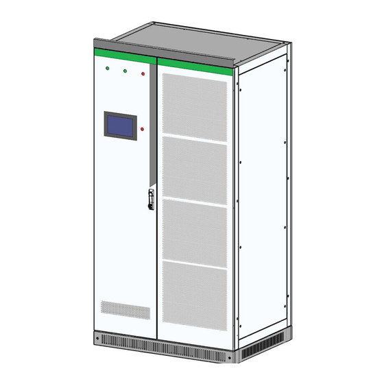
The PWS1-500KTL cabinet, width: 1100mm, height: 2,160mm (without lifting rings); depth: 800mm. The height of the lintel is 60mm and it can be taken down if there is no sufficient height into the room. The PWS1-500KTL series Bi-directional Storage Inverter is without lifting rings and can’t be lifted. -
Page 14: Rack Installation
Fig. 5-4 PWS1-500K rack wiring hole in bottom view There are two hole in each corner, only one hole need to mount bolts, the other hole is used as a spare. 5.4 Rack installation After the rack is removed to the installation position of BESS (battery energy storage system) with a forklift or a tool. - Page 15 Module fastening bolts Fig. 5-7 Module fastening bolt position in the back side of each module After confirming the above items and finished and tested, open the back door of the PCS and remove the module fastening bolts. Note: Make sure that the module fastening bolts on the back side of power module have been removed before moving the converter into the container.
-
Page 16: Installation In Container
5.5 Installation in container 5.5.1 Container internal layout distance Internal layout can be customized design according to customer’s requirements. Please contact the manufacture to know the internal layout for specific project. The distance between PCS side steel plate and container wall is no less than 50mm to ensure that the PCS can be installed inside the container. -
Page 17: Fan Installed Inside The Container
5.5.2 Fan installed inside the container When the fan is installed inside the container, its on the inner side of container door near the ventilation thermal outlet of the PCS. The Dimension of the Fan and installation position below is just an examples. Please contact manufacture to confirm the Fan position for certain project. -
Page 18: Fan Installed Outside The Container
5.5.3 Fan installed outside the container The standard external fan module is recommended and easy to install. When the fan is installed outside the container, its on the outward side of container door near the ventilation thermal outlet of the PCS. Fig. -
Page 19: Air Duct Design
Fig. 5-12 Three external fan on the outward side of the door Fig. 5-13 PWS1-500K series Fan and its corresponding Module; Relative position of Fan and back door 5.5.4 Air duct design Air duct can be customized design according to customer’s requirements. Please contact the manufacture to... -
Page 20: Installation Of Fan Module
know the air duct design for specific project. Model System air Ventilation air volume Module Inlet air area Outlet demand area PWS1-500K series 5000 M³H 6400 M³H 0.6 m 0.8 m This ventilation volume requirement is also applicable to the indoor installation. 5.5.5 Installation of Fan module Fan module (including fans and fan covers) need to be disassembled when the container commissioning and transportation. -
Page 21: Electrical Installation
For the multi-string models. Every DC input circuit branch in PCS should be able to operate independently. For multi-string models (e.g. PWS1-500KTL-XX), each DC input is independent from the other and should be connected with individual battery system. The batteries need to be connected to each branch port. - Page 22 Fig. 6-1 Design of the connection with one one-hole terminal lug Position Nut M10 and M12 Spring washer Fender washer Connection BUS bar Tin-plated one-hole terminal lug Screw M10 and M12...
- Page 23 Open the dam-board of back door and then can see the wiring copper bar as shown below. Back View 3D View Fig. 6-3 PWS1-500K series with 1 branch DC input cabinet wiring copper bars designation...
- Page 24 Table 6-3 PWS1-500K series with 1 branch DC input cabinet wiring copper bars description Position Designation Description Battery + Battery input positive pole Battery - Battery input negative pole Phase A, dimension is shown as below. Phase B Phase C Fig.
- Page 25 Front View 3D View Fig. 6-6 PWS1-500K series with 4 branch DC input cabinet wiring copper bars designation...
- Page 26 Table 6-4 PWS1-500K series with 4 branch DC input cabinet wiring copper bars description Position Designation Description Battery + Battery positive port Battery + Battery positive port Battery - Battery negative port Battery - Battery negative port Battery + Battery positive port Battery + Battery positive port Battery -...
- Page 27 Front View 3D View Fig. 6-7 PWS1-500K series with 8 branch DC input cabinet wiring copper bars designation...
- Page 28 Table 6-5 PWS1-500K series with 8 branch DC input cabinet wiring copper bars description Position Designation Description Battery + Battery positive port Battery + Battery positive port Battery - Battery negative port Battery - Battery negative port Battery + Battery positive port Battery + Battery positive port Battery -...
-
Page 29: System Grounding
Fig. 6-9 PWS1-500K series AC wiring copper bars dimension 6.1.4 System grounding The modules in the PCS realize grounding connection with the rack through hangers. As for rack grounding, the rack bottom is installed with grounded cooper bars. During wiring, refer to the following table for cable diameter. -
Page 30: Ac Port Wiring
5) Confirm wiring firmness. Rated power Copper DC line section recommendation (mm²) ≥35 mm² Each single core cable 95mm²(Single Core) or four 70mm²(Single Core) or thicker cable 500kW Three cross-sectional area. Disconnect DC distribution switch and ensure that there is no dangerous voltage in the system during wiring. The positive and negative poles of batteries cannot be connected inversely. -
Page 31: Wiring Of Terminal Strips
6.1.7 Wiring of terminal strips Except power cable connection in the whole PCS, there are also auxiliary power connection, input and output of some node signals. All of them are led to the terminal strips with cluster cables in the rack. The port definition of external wiring for terminal strips is shown in figure below. - Page 32 Fig. 6-9 Definition of terminal strip ports BMS Faults Signal External EPO Normal Close Reserved From external CAN From external RS485 From external AUX Power From external AUX Power To Container Fan To 500KVA Transformer Fan To 500KVA Transformer Temperature Control Switch Fig.
- Page 33 BMS Faults Signal 1 BMS Faults Signal 2 BMS Faults Signal 3 BMS Faults Signal 4 BMS Faults Signal 5 BMS Faults Signal 6 BMS Faults Signal 7 BMS Faults Signal 8 External EPO Normal Open Fig. 6-12 Definition of additional terminal strip ports for 8 branch DC Input Switch Fig.
-
Page 34: Communication Interface
6.2.1 Connecting the EMS over RS485 or Ethernet Sinexcel’s PCS has several different communication interfaces: Ethernet, RS-485 and CAN. When connecting to the Sinexcel or other brand EMS, the communication port is default as RS 485 as shown below. The Ethernet communication port can also used to connecting EMS according to the requirements for certain project. -
Page 35: Connecting A Bms Over Can
If the BMS use Ethernet communication port, a Ethernet-CAN protocol converter is needed . That Ethernet-CAN protocol converter should be bought by the user and its beyond Sinexcel’s scope of supply. The PCS communicates with battery management unit (BMS) to monitor battery state information, give an alarm and provide fault protection for battery according to the battery state and improve the safety of storage battery. - Page 36 is required to inspect the grounding resistance. 3) Compare ex-factory main wiring diagram provided by the manufacture and site wiring. Check whether there is any difference and judge whether such difference will affect the safe operation of energy storage system.
-
Page 37: Installation Checklist
7 Installation checklist After finishing the installation, check the list below: Mechanical installation √ There is sufficient free space in front and at the back of the unit. □ The module fastening bolts is removed □ The ambient operating conditions are within the range in specification. □... -
Page 38: Start-Up And Operation
8 Start-up and Operation Please refer to the Operation Manual for details. Possible chapter and contents. Chapter 7 Function Description Chapter 8 Operation Chapter 9 Troubleshooting... -
Page 39: Contact
• Battery type and number • Communication type • Firmware version • Error number and error message Shenzhen Sinexcel Electric Co., Ltd. Website: http://sinexcel.us/ www.sinexcel.com Add: Building 6, Area 2, Baiwangxin High-tech Industrial Park, No. 1002, Songbai Road, Nanshan District,...
Need help?
Do you have a question about the PWS1-500KTL and is the answer not in the manual?
Questions and answers