
Related Manuals for Abov A96T418GDN


Summary of Contents for Abov A96T418GDN
- Page 1 A96T418GDN Shield Board Shield Board Quick Guide Version 1.11 Global Top Smart MCU Innovator, ABOV Semiconductor www.abovsemi.com...
-
Page 2: Table Of Contents
Contents A96T418GDN Shield Board quick Guide Contents Introduction ............................ 5 User requirements .......................... 6 Hardware ..........................6 2.1.1 Starter Kit........................6 2.1.2 Shield Board ......................6 Software ..........................7 Reference documents ......................7 System requirements ......................8 ABOV website ........................8 Building and running project (Shield Board) .................. - Page 3 A96T418GDN Shield Board quick Guide List of figures List of figures Figure 1. A96T418GDN Starter Kit Board (Hardware) ................6 Figure 2. A96T418GDN Shield Board (Hardware) .................. 6 Figure 3. Compiler (Software) ......................... 7 Figure 4. Reference Documents ......................7 Figure 5.
- Page 4 List of tables A96T418GDN Shield Board quick Guide List of tables Table 1. Shield Board Description ......................11...
-
Page 5: Introduction
The starter kit board contains a debugger called “OCD”, which eliminates the need for additional devices for MCU programming and debugging. In this Quick Start Guide, we’ll discuss how to operate A96T418GDN Shield Board, as an example, step by step... -
Page 6: User Requirements
2. User requirements A96T418GDN Shield Board quick Guide User requirements Hardware Starter Kit 2.1.1 Figure 1. A96T418GDN Starter Kit Board (Hardware) Shield Board 2.1.2 Figure 2. A96T418GDN Shield Board (Hardware) -
Page 7: Software
A96T418GDN Shield Board quick Guide 2. User requirements Software Keil complier (uVision5) EVK (Library) software Figure 3. Compiler (Software) Reference documents A96T418 Starter Kit Quick Guide A96T418 Starter Kit HW Manual A96T418 User’s Manual T-TYPE LED Structure Touch Basic Algorithm Example code For detailed information, refer to the categories below. -
Page 8: System Requirements
2. User requirements A96T418GDN Shield Board quick Guide System requirements Windows PC (7, 8, 10) USB micro-B type cable Figure 5. Window PC & Mini-B cable ABOV website For detailed information about corresponding software and documents, you can visit our website at https://www.abovsemi.com. -
Page 9: Building And Running Project (Shield Board)
STKS A96T418GDN Shield Board quick Guide Building and running project (Shield Board) Building and running project (Shield Board) Running application code makes it easier to start the Shield Board. Following the steps below: Prepare the Starter kit & Shield Board Step 1. -
Page 10: Prepare The Starter Kit & Shield Board
C. LED, switch and jumper to check input/output, reset, and debugger pins OCD board configuration OCD for programming and debugging with ABOV 8-bit MCU(connected to USB port of Supports OCD Disconnection Mode (In this mode, OCD DSCL and DSDA port can be used as UART TX and UART RX, respectively) Figure 7. -
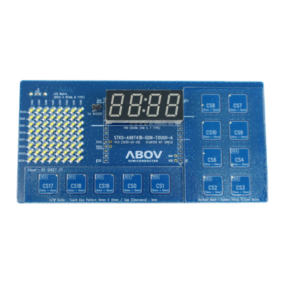
Page 11: Figure 8. A96T418Gdn Shield Board Description
STKS A96T418GDN Shield Board quick Guide Building and running project (Shield Board) Hardware components of the Shield Board Table 1. Shield Board Description Function Description Remark CS6,7,8,9,10 User SW Touch Only Pin CS0,1,2,3,4,17,18,19 User SW Touch & SEG Pin LED T-Type Segment... -
Page 12: Set Up The Starter Kit & Shield Board
Building and running project (Shield Board) A96T418GDN Shield Board quick Guide Set up the Starter kit & Shield Board Set jumpers to control the Starter Kit USB 5V Power Output On/Off Jumper OCD/UART Selection Switch External 5V Device Board(A96T418 IC included) Power On/Off Switch OCD_DSCL/OCD_DSDA or UART_TX/UART_RX (Depends on ②OCD/UART SEL SW) -
Page 13: Figure 10. Connect To Starter Kit To Use Shield Board
STKS A96T418GDN Shield Board quick Guide Building and running project (Shield Board) Connect to Starter Kit to use Shield Board Connect the header socket on the Shield board on the header pin of the Starter Kit Board. As shown in the following Figure 10. -
Page 14: Connect The Starter Kit To Your Pc
Building and running project (Shield Board) A96T418GDN Shield Board quick Guide Connect the Starter Kit to your PC PC connection via USB on the Starter Kit Connect the USB 2.0 (micro-B type) cable to the Starter Kit as shown in Figure 11. -
Page 15: Figure 12. Abov Ocd At Device Manager
STKS A96T418GDN Shield Board quick Guide Building and running project (Shield Board) When OCD is connected, it is displayed as ABOV OCD in Device Manager. OCD is a Universal Serial Bus(USB) controllers class and does not require driver installation on Microsoft Windows... -
Page 16: Stks Practice
Building and running project (Shield Board) A96T418GDN Shield Board quick Guide STKS Practice Compile with Keil uVision5 for C51 3.4.1 Install “Keil uVision5 for C51”. Open the project file provided (A96T418Proj.uvmpw). Figure 13. Execute Keil uVision5 for C51 Build the project... -
Page 17: Download & Run With Ocd
STKS A96T418GDN Shield Board quick Guide Building and running project (Shield Board) Download & Run with OCD 3.4.2 Connection : To connect the OCD, move the power switch in the direction shown below. Figure 15. OCD Connection Download : Download the hex file (t418code.hex) as shown below. -
Page 18: Figure 16. Ocd Connection
Building and running project (Shield Board) A96T418GDN Shield Board quick Guide Figure 16. OCD Connection Display on LED-Matrix(M-type) & LED-Segment(T-type) Display on LED-Matrix with the rules of 0,1,2,3,4 … C. Display on LED-Segment with the rules of 1000,2000,4000,8000,0100 …... -
Page 19: Figure 17. Touch & Display
STKS A96T418GDN Shield Board quick Guide Building and running project (Shield Board) Figure 17. Touch & Display... -
Page 20: Function Description (Using Touch Library)
Function description (Using Touch library) A96T418GDN Shield Board quick Guide Function description (Using Touch library) Touch Parameter Description touch_config.h 4.1.1 #define CSXX_USE X 4.1.1.1 ━ If you used touch channel, set X=1, otherwise set X=0. Figure 18. Touch CH activation (in touch_config.h) -
Page 21: Figure 19. Touch Clock Setting Value (In Touch_Lib.h)
STKS A96T418GDN Shield Board quick Guide Function description (Using Touch library) #define TOUCH_CLK_VAL 4.1.1.2 ━ Touch sensing clock divide select. ━ Default setting : TOUCH_FREQ_4M (0x02) Figure 19. Touch clock setting value (in touch_lib.h) #define TOUCH_CLK_OFFSET_VAL 4.1.1.3 ━ Basically, the touch sensor performs touch sensing twice at two frequencies. -
Page 22: Figure 20. Low Pass Filter Register And Capacitor Setting Value (In Touch_Lib.h)
Function description (Using Touch library) A96T418GDN Shield Board quick Guide #define TOUCH_LPF_C_VAL 4.1.1.4 #define TOUCH_LPF_R_VAL 4.1.1.5 ━ Internal Low pass filter value setting parameters Figure 20. Low Pass Filter Register and Capacitor setting value (in touch_lib.h) -
Page 23: Figure 21. Touch Sensing Mode Setting Value (In Touch_Lib.h)
STKS A96T418GDN Shield Board quick Guide Function description (Using Touch library) #define TOUCH_MODE_VAL 4.1.1.6 ━ Touch sensing mode setting value Figure 21. Touch sensing mode setting value (in touch_lib.h) ━ TS_MODE_NORMAL : In this mode, the parasitic capacitance value for each channel is not adjusted. -
Page 24: Figure 23. Sensitivity For Each Channel In Normal Mode
Function description (Using Touch library) A96T418GDN Shield Board quick Guide ━ TS_MODE_ADJUST : It is a mode that automatically adjusts the capacitance value of each channel to be the same using the IC internal capacitance. : The capacitance values for each channel are adjusted equally, so the sensitivity for each channel is adjusted similarly. -
Page 25: Figure 24. Touch Sensing Channel Port Setting Value (In Touch_Lib.h)
STKS A96T418GDN Shield Board quick Guide Function description (Using Touch library) #define TOUCH_PORT_SEL_VAL 4.1.1.7 ━ Touch sensing channel port setting ━ Default output Low Figure 24. Touch sensing channel port setting value (in touch_lib.h) #define TOUCH_VHS_VAL 4.1.1.8 ━ Applies to 'Hisense Mode' only ━... -
Page 26: Figure 25. Debounce Count
Function description (Using Touch library) A96T418GDN Shield Board quick Guide #define DETECT_DEBOUNCE_CNT_VAL 4.1.1.10 #define RELEASE_DEBOUNCE_CNT_VAL 4.1.1.11 ━ Debounce is used to remove glitch noise. ━ If the debounce count is too large, it takes a lot of time for touch recognition and release recognition, so you need to set the appropriate value. - Page 27 STKS A96T418GDN Shield Board quick Guide Function description (Using Touch library) #define TIMER_STARTUP_VAL 4.1.1.13 ━ Set stabilization time of touch sensor after IC power on (unit : 1 ms) ━ Generate Touch Key values after a set time. ━ Setting range (100 ~ 500) : default 300 #define TIMER_BASE_SAMPLE_VAL 4.1.1.14...
-
Page 28: Figure 27. Reverse Situation Parameters
Function description (Using Touch library) A96T418GDN Shield Board quick Guide #define TIMER_REVERSE_BASE_SAMPLE_VAL 4.1.1.16 ━ This feature prevents malfunction when Rawdata is outside the baseline. ━ This function sets the reverse holding time (unit: ms). ━ After this time, rawdata and basedata are matched. -
Page 29: Figure 28. Press Threshold & Release Threshold (Set 50% Rate)
STKS A96T418GDN Shield Board quick Guide Function description (Using Touch library) #define THD_DETECT_CHXX 4.1.1.18 ━ Set the threshold for each channel. ━ If the Diff data exceeds Threshold (THD), a Key detect event will occur. ━ Setting range (50 ~ 2000) #define THD_RELEASE_RATE_VAL 4.1.1.19... -
Page 30: Figure 29. Change Of Touch Data According To Touch_Sum_Cnt_Ch07
Function description (Using Touch library) A96T418GDN Shield Board quick Guide #define TOUCH_SUM_CNT_CHXX 4.1.1.20 ━ A function that allows you to adjust the touch sensitivity. ━ SUM_COUNT determines the number of consecutive sensing times for a channel. ━ The greater the setting value, the greater the sensitivity. -
Page 31: Figure 30. Baseline Trace Speed (1 Vs 5)
STKS A96T418GDN Shield Board quick Guide Function description (Using Touch library) #define BASE_TRACE_SPEED_CHXX 4.1.1.21 ━ Sets the ratio between the existing data and the current data when updating the baseline. ━ Previous value : Current value = N : 1 ━... -
Page 32: User_Function.c
Function description (Using Touch library) A96T418GDN Shield Board quick Guide user_function.c 4.1.2 void Library_Data_Assign(void) 4.1.2.1 ━ Data connection function of the variable pointer used by the Touch library. ━ If you change the contents of the function, it may affect touch sensing, so don't change it. -
Page 33: Led Parameter Description
STKS A96T418GDN Shield Board quick Guide Function description (Using Touch library) LED Parameter Description user_function.h 4.2.1 #define COMXX_EN 4.2.1.1 #define SEGXX_EN 4.2.1.2 ━ If you used COM/SEG channel, set X=1, otherwise set X=0. Figure 31. LED COM/SEG port activation... -
Page 34: Figure 32. Led Port Current Setting Value
Function description (Using Touch library) A96T418GDN Shield Board quick Guide #define LED_CURRENT 4.2.1.3 ━ This is the driving current setting parameter of the LED driver. Figure 32. LED port current setting value #define LED_USE_COM_NUM 4.2.1.4 ━ Number of COM ports used. -
Page 35: User Function Feature Description
STKS A96T418GDN Shield Board quick Guide Function description (Using Touch library) User Function Feature Description user_function.h 4.3.1 #define LED_DRV_EN X 4.3.1.1 ━ An option to control the LED via the LED driver. ━ If you are using led driver, set X=1, otherwise set X=0. -
Page 36: Figure 36. Touch/Led Independent Mode
Function description (Using Touch library) A96T418GDN Shield Board quick Guide ━ #define TS_LED_TIME_DIV 0 : More noise is generated than when used. Figure 36. Touch/LED Independent Mode... -
Page 37: Figure 37. Uart Baud Rate Setting
STKS A96T418GDN Shield Board quick Guide Function description (Using Touch library) #define UART_ENABLE X 4.3.1.3 ━ Data on Touch can be checked during project development. ━ If you use debug.c (UART), set X=1, otherwise set X=0. ━ The UART baud rate setting uses the parameter "#define DBG_BAUD_RATE" and is used as a parameter for the function "DBG_Set_Baudrate (uint8_t baud)". -
Page 38: Figure 38. Hold Key Release Event
Function description (Using Touch library) A96T418GDN Shield Board quick Guide #define HOLD_KEY_RELEASE_EN X 4.3.1.6 ━ If you are using Hold Key Release function, set X=1, otherwise set X=0. ━ If one or more keys are continuously pressed for a certain period of time (default 10s), the function is judged to be abnormal and the entire key is initialized. -
Page 39: Figure 39. Touch First Key Priority Define
STKS A96T418GDN Shield Board quick Guide Function description (Using Touch library) #define FIRST_KEY_PRIORITY X 4.3.1.7 ━ If you are using Key Priority set function, set X=1, otherwise set X=0. ━ If you enter a key set to priority, other keys are ignored (the keys with the same priority are not ignored;... -
Page 40: Figure 40. Multi Key Reset Use Channel Define
Function description (Using Touch library) A96T418GDN Shield Board quick Guide #define MULTI_KEY_RESET X 4.3.1.8 ━ Set X=1 if you are using the multi-key reset function, otherwise set X=0. ━ Pressing more than a set number of channels with the multi-key reset function enabled will reset the key. - Page 41 STKS A96T418GDN Shield Board quick Guide Function description (Using Touch library) #define TOUCH_RREQ_SEL_EN X 4.3.1.9 ━ If you are using Touch Frequency Change function, set X=1, otherwise set X=0. ━ This function calculates Diff data by selecting a frequency with a small noise among the two frequencies.
-
Page 42: Main.c
Function description (Using Touch library) A96T418GDN Shield Board quick Guide main.c 4.3.2 void Init_GPIO(void) 4.3.2.1 ━ Default GPIO set, output Low void Init_Touch(void) 4.3.2.2 ━ Touch sensing mode and touch related data assign function. ━ If you change the contents of the function, it may affect touch sensing, so don't change it. -
Page 43: Revision History
STKS A96T418GDN Shield Board quick Guide Revision history Revision history Date Revision Description 20.04.10 1.00 Document created 21.01.04 1.01 Function name, variable name modified 21.01.04 1.01 ts_Get_Key() Function deleted. ts_detect_key variable added 21.01.04 1.01 TS_Set_CH_THD(u8 ch_idx, s16 tdh), u8 ch -> u8 ch_idx 22.11.01... - Page 44 ABOV Semiconductor ("ABOV") reserves the right to make changes, corrections, enhancements, modifications, and improvements to ABOV products and/or to this document at any time without notice. ABOV does not give warranties as to the accuracy or completeness of the information included herein. Purchasers should obtain the latest relevant information of ABOV products before placing orders.
Need help?
Do you have a question about the A96T418GDN and is the answer not in the manual?
Questions and answers