
Subscribe to Our Youtube Channel
Related Manuals for Abov A31G324RLN


Summary of Contents for Abov A31G324RLN
- Page 1 A31G324RLN Shield Board Implementation Guide Application Note Version 1.00 Global Top Smart MCU Innovator www.abovsemi.com...
-
Page 2: Table Of Contents
Contents A31G324RLN shield board implementation guide Contents Introduction ............................ 5 User requirements .......................... 6 Hardware ..........................6 Software ..........................7 Reference documents ......................7 System requirements ......................8 ABOV website ........................8 Building and running project (Shield board) ................... 9 Prepare the Starter Kit and Shield board ................ - Page 3 Figure 15. Create EBI_LCD Project from Pack Installer ............... 16 Figure 16. Open EBI_LCD Project from Pack Installer ................. 16 Figure 17. Download Evaluation Kit (Example Source) from ABOV Website ........17 Figure 18. Compile Result on uVision5 (EBI_LCD Project) ..............18 Figure 19.
- Page 4 List of tables A31G324RLN shield board implementation guide List of tables Table 1. Shield Board Description ......................11 Table 2. LCD & User Switch Operation ....................21 Table 3. Buzzer & User Switch Operation ..................... 28...
-
Page 5: Introduction
SW to the target device. Using this CMSIS-DAP debugger (A-Link), you can eliminate the needs for additional devices when programming and debug the MCU. In this document, you can learn a method how to operate the A31G324RLN Shield board, as an example, step by step. -
Page 6: User Requirements
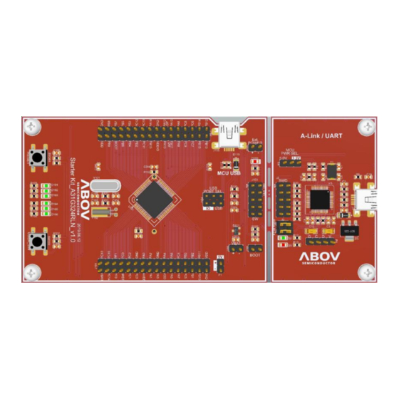
A31G324RLN shield board implementation guide User requirements Hardware In this section, you will see the Starter Kit board and Shield board of A31G324RLN in Figure 1 and Figure 2 respectively. Figure 1. A31G324RLN Starter Kit Board (Hardware) Figure 2. A31G324RLN Shield Board (Hardware) -
Page 7: Software
A31G324RLN shield board implementation guide 2. User requirements Software Keil compiler in the Starter Kit board features the followings: Keil complier (uVision5) Keil MDK5 software pack (including Starter Kit sample code) or EVK software Figure 3. Compiler (Software) -
Page 8: System Requirements
2. User requirements A31G324RLN shield board implementation guide System requirements Windows PC (7, 8, 10) USB mini-B type cable Figure 5. Window PC & Mini-B Cable ABOV website For detailed information about corresponding software and documents, you can visit our website at https://www.abovsemi.com. -
Page 9: Building And Running Project (Shield Board)
A31G324RLN shield board implementation guide 3. Building and running project (Shield board) Building and running project (Shield board) Running application code makes it easier to start the Shield board. Following the steps below: Step 1. Prepare the Starter Kit & Shield Board Step 2. -
Page 10: Prepare The Starter Kit And Shield Board
Pin Headers connected to MCU C. LED, switch and jumper to check input/output, reset, and debugger pins A-Link (CMSIS-DAP/UART) board configuration A-Link for programming and debugging with ABOV 32-bit MCU(connected to USB port of Supports UART Figure 7. Starter Kit Board... -
Page 11: Hardware Components Of The Shield Board
Hardware components of the Shield board Table 1. Shield Board Description Function Description Remark User SW User SW User SW or EBI Reset Pin Buzzer PA7 / TIMER40OUT EBI to LCD EBI 8bit bus AT25080B-SSHL-B EEPROM SPI(20MHz, 8bit) Figure 8. A31G324RLN Shield Board Description... -
Page 12: Set Up The Starter Kit And Shield Board
3. Building and running project (Shield board) A31G324RLN shield board implementation guide Set up the Starter Kit and Shield board 3.2.1 Set jumpers to control the Starter Kit The Starter Kit uses USB power-① Choose 3.3V and 5.0V (check the maximum operation voltage by referring to the specification sheet). -
Page 13: Connect To Starter Kit To Use Shield Board
A31G324RLN shield board implementation guide 3. Building and running project (Shield board) 3.2.2 Connect to Starter Kit to use Shield board Connect the header socket of the Shield board to the header pin of the Starter Kit board as shown in Figure 10. -
Page 14: Connect The Starter Kit To Your Pc
3. Building and running project (Shield board) A31G324RLN shield board implementation guide Connect the Starter Kit to your PC 3.3.1 PC connection via USB on the Starter Kit Connect the USB 2.0 (mini-B type) cable to the Starter Kit as shown in Figure 11. -
Page 15: Ebi_Lcd (User Switch)
A31G324RLN shield board implementation guide 3. Building and running project (Shield board) EBI_LCD (user switch) 3.4.1 Running the EBI_LCD project Before downloading the EBI_LCD example, Keil uVision5 for ARM must be installed on your PC. Execute “Keil uVision5”. Click the Pack Installer icon to run the installer. -
Page 16: Figure 15. Create Ebi_Lcd Project From Pack Installer
3. Building and running project (Shield board) A31G324RLN shield board implementation guide Create a Starter Kit example in Pack Installer. When the selected example is copied (①), a dialog box (②) appears to prompt you to choose a destination folder. -
Page 17: Figure 17. Download Evaluation Kit (Example Source) From Abov Website
If you want to use Evaluation Kit (example source), you can download it from ABOV official website. Once downloading is complete, unzip the file and run EBI_LCD uVision5 in the example directory. See the Keil Setting Guide for detailed instructions. Figure 17. Download Evaluation Kit (Example Source) from ABOV Website... -
Page 18: Compiling Ebi_Lcd
3. Building and running project (Shield board) A31G324RLN shield board implementation guide 3.4.2 Compiling EBI_LCD Execute “Rebuild all target files” on the created uVision5 (EBI_LCD Project). Select Rebuild (①) to proceed with compilation. The compile result can be checked in Build Output (②). Make sure there are no errors in the project. -
Page 19: Downloading Ebi_Lcd
A31G324RLN shield board implementation guide 3. Building and running project (Shield board) 3.4.3 Downloading EBI_LCD If the compilation finishes without any error, you can begin programming the Starter Kit. Check the followings if errors occur during the setup process. Check that CMSIS-DAP Debugger (①) is selected in the Debug tab (use CMSIS-DAP for A-Link). -
Page 20: Debugging Ebi_Lcd
3. Building and running project (Shield board) A31G324RLN shield board implementation guide 3.4.4 Debugging EBI_LCD Debugging in Keil uVision5 Run Start/Stop Debugger Session (①) to enter debugger mode. The Starter Kit must be connected for real-time, interactive debugging. In Keil debugger mode, the program can be executed by run/step. -
Page 21: Checking The Ebi_Lcd Operation
A31G324RLN shield board implementation guide 3. Building and running project (Shield board) 3.4.5 Checking the EBI_LCD operation How to check the EBI_LCD operation After downloading the EBI_LCD program, re-apply the power (removing the USB cable) to check whether the LCD is Flicker. -
Page 22: Buzzer (User Switch)
3. Building and running project (Shield board) A31G324RLN shield board implementation guide Buzzer (user switch) 3.5.1 Running the Buzzer project Before downloading the Buzzer example, Keil uVision5 for ARM must be installed on your PC. Execute “Keil uVision5”. Click the Pack Installer icon to run the installer. -
Page 23: Figure 25. Create Buzzer Project From Pack Installer
A31G324RLN shield board implementation guide 3. Building and running project (Shield board) Create a Starter Kit example in Pack Installer. When the selected example is copied (①), a dialog box (②) appears to prompt you to choose a destination folder. -
Page 24: Figure 27. Download Evaluation Kit (Example Source) From Abov Website
If you want to use Evaluation Kit (example source), you can download it from ABOV official website. Once downloading is complete, unzip the file and run Buzzer uVision5 in the example directory. See the Keil Setting Guide for detailed instructions. Figure 27. Download Evaluation Kit (Example Source) from ABOV Website... -
Page 25: Compiling Buzzer
A31G324RLN shield board implementation guide 3. Building and running project (Shield board) 3.5.2 Compiling Buzzer Execute “Rebuild all target files” on the created uVision5 (Buzzer Project). Select Rebuild (①) to proceed with compilation. The compile result can be checked in Build Output (②). Make sure there are no errors in the project. -
Page 26: Downloading Buzzer
3. Building and running project (Shield board) A31G324RLN shield board implementation guide 3.5.3 Downloading Buzzer If the compilation finishes without any error, you can begin programming the Starter Kit. Check the followings if errors occur during the setup process. Check that CMSIS-DAP Debugger (①) is selected in the Debug tab (use CMSIS-DAP for A-Link). -
Page 27: Debugging Buzzer
A31G324RLN shield board implementation guide 3. Building and running project (Shield board) 3.5.4 Debugging Buzzer Debugging in Keil uVision5 Run Start/Stop Debugger Session (①) to enter debugger mode. The Starter Kit must be connected for real-time, interactive debugging. In Keil debugger mode, the program can be executed by run/step. -
Page 28: Checking The Buzzer Operation
3. Building and running project (Shield board) A31G324RLN shield board implementation guide 3.5.5 Checking the Buzzer operation How to check the Buzzer operation After downloading the Buzzer program, re-apply the power to check whether the Buzzer operates. Table 3. Buzzer & User Switch Operation... -
Page 29: Eeprom (Use Spi In Usart)
A31G324RLN shield board implementation guide 3. Building and running project (Shield board) EEPROM (use SPI in USART) 3.6.1 Running the EEPROM project Before downloading the EEPROM example, Keil uVision5 for ARM must be installed on your PC. Execute “Keil uVision5”. -
Page 30: Figure 35. Create Eeprom Project From Pack Installer
3. Building and running project (Shield board) A31G324RLN shield board implementation guide Create a Starter Kit example in Pack Installer. When the selected example is copied (①), a dialog box (②) appears to prompt you to choose a destination folder. -
Page 31: Figure 37. Download Evaluation Kit (Example Source) From Abov Website
If want to use Evaluation Kit (example source), you can download it from ABOV official website. Once downloading is complete, unzip the file and run EEPROM uVision5 in the example directory. See the Keil Setting Guide for detailed instructions. Figure 37. Download Evaluation Kit (Example Source) from ABOV Website... -
Page 32: Compiling Eeprom
3. Building and running project (Shield board) A31G324RLN shield board implementation guide 3.6.2 Compiling EEPROM Execute “Rebuild all target files” on the created uVision5 (EEPROM Project). Select Rebuild (①) to proceed with compilation. The compile result can be checked in Build Output (②). Make sure there are no errors in the project. -
Page 33: Downloading Eeprom
A31G324RLN shield board implementation guide 3. Building and running project (Shield board) 3.6.3 Downloading EEPROM If the compilation finishes without any error, you can begin programming the Starter Kit. Check the followings if errors occur during the setup process. Check that CMSIS-DAP Debugger (①) is selected in the Debug tab (use CMSIS-DAP for A-Link). -
Page 34: Debugging Eeprom
3. Building and running project (Shield board) A31G324RLN shield board implementation guide 3.6.4 Debugging EEPROM Debugging in Keil uVision5 Run Start/Stop Debugger Session (①) to enter debugger mode. The Starter Kit must be connected for real-time, interactive debugging. In Keil debugger mode, the program can be executed by run/step. -
Page 35: Checking The Eeprom Operation
A31G324RLN shield board implementation guide 3. Building and running project (Shield board) 3.6.5 Checking the EEPROM operation How to check the EEPROM operation After downloading the EEPROM program, re-apply the power to check whether the EEPROM operates. 1. Write Byte & Erase Byte 2. -
Page 36: Revision History
Revision history A31G324RLN shield board implementation guide Revision history Date Version Description 20.12.04 1.00 Document created... - Page 37 ABOV Semiconductor ("ABOV") reserves the right to make changes, corrections, enhancements, modifications, and improvements to ABOV products and/or to this document at any time without notice. ABOV does not give warranties as to the accuracy or completeness of the information included herein. Purchasers should obtain the latest relevant information of ABOV products before placing orders.
Need help?
Do you have a question about the A31G324RLN and is the answer not in the manual?
Questions and answers