Table of Contents
Advertisement
Quick Links
Advertisement
Table of Contents

Subscribe to Our Youtube Channel
Related Manuals for SOLZAIMA ACQUA ECO


Summary of Contents for SOLZAIMA ACQUA ECO
- Page 1 Instruction Manual English Water Central Heating Stoves Models ACQUA ECO ACQUA ECO PV ECOFOGO ECO MYTHO ECO MYTHO ECO PV ZAIMA ECO Please read the instructions carefully before installing, using and maintaining of equipment. The instruction manual is an integral part of the product.
- Page 2 * Technical assistance must be carried out by your Installer or Solution Provider, except in special cases after evaluation by the installer or technician responsible for the service, who will contact SOLAIMA if deemed necessary. Contact for technical assistance: www.solzaima.pt apoio.cliente@solzaima.pt Address: Rua dos Outarelos; No. 111; 3750-362 Belazaima do Chao...
-
Page 3: Table Of Contents
Index SOLZAIMA ........................1 TECHNICAL CHARACTERISTICS ..................2 GENERAL MEASURES ..................... 4 KNOW THE EQUIPMENT ....................10 MATERIALS OF THE RECUPERATORS ................13 INSTALLATION ......................15 6.1................19 IRCULATION OF AIR AND FLUE GASES 6.1.1..........19 HEORETICAL NOTIONS FOR THE INSTALLATION OF CHIMNEYS 6.1.2. -
Page 5: Solzaima
As a result of the persistence and unconditional support of its network of partners, Solzaima is today a leader in the production of biomass heating, whose best example is the water central heating recuperators and its range of pellet salamanders. -
Page 6: Technical Characteristics
2. Technical characteristics The Central Water Heating stoves are equipment intended for space heating and water heating for use in central heating installations and for domestic use. For this, a pre- installation of central heating and an accumulator with heat exchanger are necessary if you want to heat sanitary water. - Page 7 Acqua Acqua Ecofire Mytho Mytho Zaima Features Echo Eco PV Echo Eco PV Echo Weight Width Height 1200 1200 Depth Diameter smoke discharge pipe Maximum heating volume m³ Rated thermal input 28,2 28.2 21,7 21,7 2 1.7 21,7 Air thermal power Thermal power water 18,7 18,7...
-
Page 8: General Measures
3. General measures Acqua Eco Figure 1... - Page 9 Acqua Eco PV Figure 2...
- Page 10 Ecofogo Eco Figure 3...
- Page 11 Mytho Eco Figure 4...
- Page 12 Mytho Eco PV Figure 5...
- Page 13 Zaima Eco Figure 6...
-
Page 14: Know The Equipment
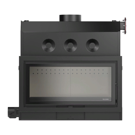
4. Know the equipment Acqua Eco Smoke output Optional anti- packaging kit Vermiculit plaquesand Input regulator from ar Door lock Figure 7 Acqua Eco PV Smoke output Optional anti- packaging kit Vermiculit plaquesand Door lock Input regulator from Figure 8... - Page 15 Ecofogo Eco Smoke output Optional anti- packaging kit Vermiculit plaquesand Input regulator from ar Door lock Figure 9 Mytho Eco Smoke output Optional anti- packaging kit Vermiculit plaquesand Input regulator from ar Door lock Figure 10...
- Page 16 Mytho Eco PV Smoke output Optional anti- packaging kit Vermiculit plaquesand Door lock Input regulator from ar Figure 11 Zaima Eco Smoke output Optional anti- packaging kit Vermiculit plaquesand Input regulator from ar Door lock Figure 12...
-
Page 17: Materials Of The Recuperators
In the ECOFOGO ECO, MYTHO ECO and ACQUA ECO models, the door is made of 2.5 mm plate, in the ACQUA ECO PV and MYTHO ECO PV models with 3.0 mm. In the ZAIMA ECO model, the door and rim are made of cast iron. The ash drawer on all models is 1.5mm. - Page 18 The anti-packaging kit is a mechanical safety system that prevents the equipment from being damaged by an excess of temperature due to, for example: damaged pump, electric current cut, etc. The kit consists of a copper coil welded to a cap that is bolted to the body by replacing the blind cap with 8 M8 screws.
-
Page 19: Installation
6. Installation Please note: all local regulations and standards must be complied with when installing this equipment. Check, immediately upon receipt, that the product is complete and in good condition. If there is any defect or malfunction, do not install the equipment and request the presence of the equipment supplier or a technician of the brand on site. - Page 20 - Insert the first deflector plate diagonally and place it on top of the upper brackets, place it horizontally and lower it slowly so that the plate is centered between the side brackets (red in the image) and leaning against the front of the body of the equipment Figure 14 - Insert the second deflector plate in the same way as the first, up to the supports in red.
- Page 21 Figure 15 - The air intake regulator can be installed on both the right and left side of the recuperator. On the side where the air intake regulator is not installed, the cover should be placed. To...
- Page 22 fix both the air intake regulator and the lid, we must use the screws that are in the bag inside the recuperator. Figure 16 The air intake for combustion can be done in two distinct ways: Leaving the air intake regulator free and installing ventilation grilles to allow air to enter the space where the recuperator is installed.
-
Page 23: Circulation Of Air And Flue Gases
your stove at the level of combustion and draft. Always confirm that the depression one meter above the recuperator is at least 12Pa. Installing an air intake duct. A 100mm diameter pipe can be connected to the air control damper inlet and channeled to the outside of the house. The length of this pipe should be as short as possible and it should be ensured that the airflow is not blocked and that the air current measured at one meter above the unit is 12Pa or higher. - Page 24 downwind causes a decrease in the depression in the chimney, sometimes causing positive pressure effects, which means that it nullifies the capacity and extraction of the chimneys. A predominantly lateral wind has an effect that will depend on the way the chimney is mounted.
-
Page 25: Installation Advice
Figure 18 6.1.2. Installation advice This appliance must be installed in a place where outside air can enter freely. Any air intake grates must be placed in a place that is not susceptible to blockage, so that there is sufficient air at the installation site, avoiding poor draught; The combustion air enters the recuperator through a system controlling the intensity of the burning. - Page 26 Figure 19 A single-walled pipe, installed outside or in areas subject to thermal variations, gives rise to condensation of the water vapor present in the flue gases, so it is advisable to use an insulated double-walled pipe. The joints of the pipes must be very well sealed so that possible cracks do not allow air to enter.
- Page 27 Figure 21 Pipe joints must not allow bottlenecks (reductions) and the inner walls must be perfectly smooth and free from obstacles; Hats should be placed in such a way that they do not hinder printing. Minimum distance equal to pipe diameter Incorrect Correct...
-
Page 28: Installation Location Requirements
The same chimney should not be used for more than one appliance or open fireplace. In the collective chimneys each one must reach the windows that must be at the same level, independently, so that the air circulation expels the gases out. If the chimney is brick it should not be too wide, because the smoke when spreading cools and damages the draw. - Page 29 In these recuperators, the intake of air for combustion can be carried out in two different ways: By means of ventilation grids. Installing air intake grids for the insertion area of the appliance, which must be done as shown in the following diagram, in order to ensure the proper functioning of the recuperator.
- Page 30 Cabin air outlet Cabin air outlet Side access Passenger Air intake Passenger compartment from outside compartment air intake air intake Figure 24...
- Page 31 Installing an air intake duct. A 100mm diameter pipe can be connected to the air control damper inlet and channeled to the outside of the house. The length of this pipe should be as short as possible and it should be ensured that the airflow is not blocked and that the air current measured at one meter above the unit is 12Pa or higher.
-
Page 32: Hydraulic Installation
6.3. Hydraulic installation Chapter 12 "Installation Schemes" contains the possible connection schemes in the context of a central heating installation, with or without domestic water heating. The minimum connection temperature of the circulation pump must be 60°C in order to avoid condensation inside the recuperator. The pump must be applied in the return circuit of the radiators, where the temperature is lower. - Page 33 If the installation option is by closed expansion vessel, this should not be less than 25 liters and the safety valves should be 3 bars (suitable for use up to 90°C). Additional placement of a pressure and temperature safety valve (3bar / 90°C) is advised. For the purpose of emptying the appliance, a tap must be placed in one of the outlets provided for that purpose in the lower side of the appliance.
-
Page 34: Optional Trim Rim
The finishing rim is an optional piece, which you can purchase to improve the aesthetics of the Ecofogo Eco, Mytho Eco, Mytho Eco PV, Acqua Eco and Acqua Eco PV recuperators. In the Zaima Eco model the rim is in casting and will be included in the equipment. You can choose between wide, narrow and narrow glass rims. - Page 35 Rim 4,4cm P=4cm glass ref: MO1160P030 Rims for Mytho Eco PV: Rim 7,4cm P=4cm ref: MO1160P076...
- Page 36 Rim 4.4cm P=4cm ref: MO1160P082 Rim 7,4cm P=6cm ref: MO1160P090...
- Page 37 Rim 4,4cm P=6cm ref: MO1160P089 Rims for Acqua Eco: Rim 7,4cm P=4cm ref: MO01160G020...
- Page 38 Rim 4,4cm P=4cm ref: MO01160G019 Rims for Acqua Eco PV: Rim 7,4cm P=4cm ref: MO01160P084...
- Page 39 Rim 4.4cm P=4cm ref: MO1160P083 Rim 7,4cm P=6cm ref: MO1160P088...
- Page 40 Rim 4,4cm P=6cm ref: MO01160P087 If you want to install the finishing hoops in the Ecofogo Eco, Mytho Eco, Mytho Eco PV, Acqua Eco and Acqua Eco PV recuperators , you must proceed as follows: Open the door. Place the 4 M4 screws supplied with the rim, but do not tighten them completely.
-
Page 41: Transport Bars
6.4.2. Transport bars The equipment is very heavy and bulky. In order to be able to move it more easily, we recommend that you buy the transport bar kit. This kit is an optional accessory that can be purchased separately. It consists of 4 steel rods painted black with a threaded end to attach very firmly to the body of the equipment. - Page 42 weight and bumps or damage. Remove the 4 screws DIN 6921 M6x20mm with the help of a 10mm wrench. If you have the carry bars, screw them until they are firm. You must have the equipment as shown in the following image. Figure 29 Move the equipment on the pallet so that one side of the equipment is in the air, do not go beyond the middle of the equipment so that it is stable on the pallet when it is at...
- Page 43 Put a wheel on the two corners that are in the air, note that there are 2 different types. Secure them to the base with the 2 screws you removed earlier. Figure 31 Move the equipment over the pallet, leaving the left front corner in the air, as shown in the image.
-
Page 44: Auxiliary Leveling Table
Move the equipment on the pallet leaving the left rear corner in the air, as shown in the image. Place the wheel and fix it with the screw, as was done with the previous wheels. Figure 33 Lift the equipment from one side and completely remove the pallet. Now you can move the equipment easily and take it to your final location. - Page 45 The side table is recommended for any model, but especially in the case of the Mytho Eco PV and Acqua Eco PV, due to the door opening and closing system. The table assembly process is practically the same for all models, the only thing that changes is the size, but it is the same philosophy.
- Page 46 The equipment is very heavy, if it has no machinery, it needs to be handled by more than one person. The first step is to assemble a series of parts so that they are ready before you start moving the equipment. Place the 4 feet levelers on the 4 vertical columns, screwing them to the bottom.
- Page 47 help of a 10mm wrench. If you have the carry bars, screw them until they are firm. You must have the equipment as shown in the following image. Figure 36 Move the equipment on the pallet so that one side of the equipment is in the air, do not go beyond the middle of the equipment so that it is stable on the pallet when it is at rest.
- Page 48 Tilt the equipment using the transport bars, to gain the necessary space and place the first subset that we have assembled. Fix the subassembly by placing two of the screws we removed earlier (DIN 6921 M6x20mm) and secure them tightly. Figure 38 With the help of the transport bars, lift the equipment so that the pallet can be removed.
- Page 49 Place the second subassembly in the position you can see in the following image, use the other 2 screws removed earlier (DIN 6921 M6x20mm) to attach the subassembly to the equipment. Pay special attention to the position of the front and rear rails, as you can see in the image below, they should be inside the vertical columns of the subassembly.
- Page 50 With the machine in its final position, perform the leveling using the 4 feet of leveling and a level that we recommend to place on the door rim to level the left right position and inside the combustion chamber to level the front and back. Remember to check again when you have finished both positions, as changing one level may affect the other.
-
Page 51: Anti-Packaging Kit
6.4.5. Anti-packaging kit On the right side of the recuperator there is the possibility of installing an anti- packaging kit. This kit is an optional accessory that you can purchase separately. You can buy as an accessory with the following reference: PA1026P019 –... - Page 52 Place the kit in the same position as the cap, making sure that the silicone gasket is centered in relation to the holes. Place the screws without tightening them completely and after verifying that everything is correctly positioned, tighten them alternately to ensure correct tightness.
- Page 53 Note: Do not connect the anti-packaging kit to a water supply that relies on electricity for service, e.g., well water. The circuit that supplies the anti-packaging kit must be independent of the heating circuit to which the recuperator is connected. Before connecting the thermal discharge valve, check the direction of circulation of the water, as a rule, indicated with an arrow on the valve body.
-
Page 54: Main Parts Of The Recuperator
7. Main parts of the recuperator Smoke outlet Automatic Ø200mm intake regulator Cajón de or sheath Is F- cenizas 3/4" safety valve temperature probe Fluid sa ida or probe dthe thermostat F- 1" Bearings for fixing transport tools Air inlet Ø100mm Door closing and combustion... - Page 55 Cover for installation anti packaging kit Bearings fixing transport tools Vermiculit plaquesand Air inlet cover Return or emptying / filling of F-1" fluid Ash grill and drawer Figure 49...
-
Page 56: Instructions For Use
20%) to achieve efficient combustion, avoid creosote deposit in the smoke pipe and glass and minimize the oxidation of the equipment. Table 2 - List of the Type of Firewood that can be used in a SOLZAIMA Heat Recovery Unit, its Geographical Distribution and Calorific Value/Reactions... -
Page 57: Power
In this way, energy efficiency alone can lead to significant economic and environmental savings. The Ecofogo ECO, Mytho Eco, Mytho Eco PV, Acqua Eco, Acqua Eco PV and Zaima Eco recuperators have an efficiency of 80%, being well above what the standard requires and... -
Page 58: First Use
In a recuperator with a yield of 50% (class 3), it is necessary to consume 2.4 kg of firewood In a Solzaima recuperator with a yield of 75% (class 1), it is necessary to consume only 1.6 kg of firewood Figure 50 8.2. -
Page 59: Instructions For Use Of The Recuperator
In the central part under the door, you will find the hole to fit the tool in order to move the combustion control safely. In the Ecofogo Eco, Mytho Eco, Zaima Eco and Acqua Eco models, the tool is inserted horizontally into the hole, as can be seen in the following images. - Page 60 →This combustion control interval is used when the recuperator is burning stably and we want to control the speed and power of combustion. The closer we get to the central point, the more speed and power we will get, but always with a high efficiency. Figure 54 From the central point of the control to the rightmost position, the primary air is progressively opened while the secondary air remains 100% open in this zone.
-
Page 61: Firing
8.3.2. Firing (a) fully open the combustion control (completely on the right); b) Place pine cones (preferably) or lighters, on the ash grid; c) Place small firewood, stacked horizontally; d) To facilitate ignition and avoid condensation as much as possible, leave the door open 2 or 3 fingers to maximize air intake. - Page 62 When refueling, we recommend that you use a load of 4.8kg for the ECOFOGO ECO, MYTHO ECO, ACQUA ECO, ACQUA ECO PV and ZAIMA ECO models. Refill the recuperator before the previous load is completely burned, to facilitate the continuation of combustion.
-
Page 63: Safety
8.4. Safety The metal parts, accessible to the user, reach high temperatures. Avoid contact with the warmer parts. Whenever you need to put firewood or meet the equipment when it is in operation, you should wear a heat-resistant glove or any other protection that prevents the transmission of heat. -
Page 64: Daily Cleaning
8.5.1. Daily cleaning The routine cleaning that will have to be done by the user will depend on the amount of firewood burned, the quality of the wood and the temperature reached in the recuperator. We recommend that this cleaning be done the day after the use of the recuperator. -
Page 65: Additional Cleaning
Figure 59 Pull up the iron bar from the ash drawer to remove it and empty the contents in a safe place, remember that it may contain hot embers among the ashes. If when removing the ash drawer you see any ash residue inside, you should also remove it. - Page 66 up the chimney or the places where smoke circulates and dirt can accumulate must also be cleaned. Disassemble the deflector plates. It is recommended to start by removing the ➔ deflector plates from the inside of the recuperator. To remove them, you must follow the opposite steps described in section 6: Installation.
- Page 67 Figure 62 Remove the 2 vermiculite plates from the back of the chamber, to remove these ➔ plates first move them upwards about 10mm and then pull the bottom towards the door so that it rotates at its top, then let it go down so that it is free of the plate that fixed it.
- Page 68 Figure 65 Remove the 2 vermiculite plaques from the sides of the chamber, these plates are ➔ unimpeded when removing the previous ones. Figure 66 In the next step you will have to use an Allen No. 5 wrench to remove the 4 screws ➔...
- Page 69 Remove the 2 screws (DIN 912 M6x14) with an Allen No. 5 wrench that secure the ➔ plate in order to separate the air control connection. Figure 68 Remove the sheet metal by lifting it from the side closest to the front panel using ➔...
- Page 70 In order to remove the combustion control, it is necessary to remove the part ➔ where the tool we use to adjust the position of the combustion control is mounted. This part is fixed by means of 2 screws, unscrew these 2 screws about 5mm (do not remove them completely, so that it is easier to assemble the system later) and remove this part.
-
Page 71: Remove The Door
With all the interior free you can clean the recuperator in a simple way. We ➔ recommend cleaning from top to bottom using a brush and an ash cleaner. As a lot of dust will be created, you should use all the necessary protections, such as a mask, goggles, etc. - Page 72 Figure 75 Rotate the door slightly so that the bottom of the door is off the rim. ➔ Lower the door so that it can be removed from the body. ➔ Figure 76...
-
Page 73: Adjust The Port
8.5.4. Adjust the port With use and over time, the cord that seals the door to the rim of the body wears out and loses qualities. To ensure that the cord continues to have the necessary pressure to ensure the tightness of the stove, the space between the door and the rim can be adjusted as follows: Open the door. -
Page 74: Troubleshooting Some Issues
9. Troubleshooting some issues Problem Solutions . Check the humidity of the firewood (it will have to be less than 20%)). The glass gets dirty . Increase the intensity of the burning by opening the secondary air regulator a little more. -
Page 75: End Of Life Of A Recuperator
Solzaima seeks to know and study the national forest park, responding efficiently to energy requirements always with the care to safeguard biodiversity and natural wealth, essential for the quality of life of the Planet. -
Page 76: Installation Schemas
12. Installation Schemas The installations illustrated below are valid for all models in this manual. Scheme 1 – Installation for central heating (AC). Note: in the case of installing with closed vessel put pressure and temperature discharge valve. Scheme 2 – Installation for central heating (AC) and Sanitary Hot Water (ACS) - Page 77 Scheme 3 – Installation for central heating (AC) and Sanitary Hot Water (ACS) with solar panel...
- Page 78 Scheme 4 – Installstion towards heating central (AC) e ÁWaters Hot Sanitárias (ACS) com Paisolar nel e thePoio of syrupira a pellets...
- Page 80 Symbology Open expansion vessel...
-
Page 81: Glossary
13. Glossary * bar: unit of pressure and equals exactly 100,000 Pa. This pressure value is very close to that of the standard atmospheric pressure. * lime (Calorie): is expressed by the amount of heat necessary to increase one degree centigrade the temperature of one gram of water. - Page 82 * Calorific Value: also called specific heat of combustion. It represents the amount of heat released when a given amount of fuel is burned completely. The calorific value is expressed as calories (or kilocalories) per unit weight of fuel. * Polegada: unit of length used in the British imperial system of measurements. One inch is 2.54 centimeters or 25.4 millimeters.
-
Page 83: Warranty
The activation of the Warranty presupposes the prior and correct identification of the Product object of the same with Solzaima, S.A., to be promoted through the indication of the data of the packaging of the Product contained either in the respective purchase invoice, or in the plate of characteristics of the Product (model and serial number). - Page 84 3.5 In order to exercise its rights, and provided that the deadline indicated in 3.1 is not exceeded, the Buyer must report in writing to Solzaima, S.A. the lack of conformity of the Product within a maximum period of: 3.5.160 (sixty) days from the date on which it has detected it, in the case of...
- Page 85 An installation of a Product that does not comply with the manufacturer's specifications and/or that does not comply with the legal regulations on this matter, will not give rise to the application of this Warranty. Whenever a Product is installed outside, it must be protected against meteorological effects, namely rain and winds.
- Page 86 The means necessary for access to them will be made available by the Buyer, being in charge of any charges arising therefrom. 3.17The Warranty is valid for the Products and equipment sold by Solzaima SA only and exclusively within the geographical and territorial area of the country where the sale of the...
- Page 87 4.Circumstances excluding the application of the Guarantee The following cases are excluded from the Warranty, and the total cost of the repair shall be borne by the Buyer: 4.1.Products with more than 2000 operating hours; 4.2.Refurbished and resold products. 4.3.Maintenance operations, adjustments of the Product, start-ups, cleaning, elimination of errors or anomalies that are not related to deficiencies of equipment components and replacement of batteries;...
- Page 88 4.10.Products that have been modified or handled by persons outside the Official Technical Services of the brand and consequently without explicit authorization from Solzaima, S.A.; 4.11.As breakdowns caused by external agents (rodents, birds, spiders, etc.), atmospheric and/or geological phenomena (earthquakes, storms, frosts, hail, thunderstorms, rains, etc.), aggressive humid or saline environments (e.g.
- Page 89 Buyer and upon availability of the Producer. 5.Inclusion of the Warranty Solzaima, S.A. will correct, at no charge to the Buyer, the defects covered by the Warranty, by repairing the Product. The replaced Products or Components will become the property of Solzaima, S.A.
- Page 90 Used Parts from the moment they are removed from the equipment set acquire the status of waste. Solzaima, as a producer of waste within the scope of its activity, is obliged by the legislation in force to deliver it to a licensed entity that carries out the necessary waste management operations in accordance with the law and therefore prevented from giving them another destination, whatever it may be.
-
Page 91: Declaration Of Performance
15. Declaration of Performance ECLARAÇÃO DE ESEMPENHO ECLARACIÓN RESTACIONES ECLARATION OF ERFORMANCE ÉCLARATION DE ERFORMANCE ICHIARAZIONE DELLE PRESTAZIONI DD-078 º Código de identificação único do produto-tipo | Código de identificación único del tipo de producto | Unique identification code of the product type | Le code d'identification unique du type de produit | Codice unico di identificazione del tipo di prodotto –... - Page 92 Relatório de ensaio | Informe de la prueba | Test report | Rapport d’essai | Rapporto di prova CEE/0026/21-1 Desempenho declarado | Desempeño declarado | Declared performance | Performance déclarée | Dichiarazione di prestazione Especificações técnicas harmonizadas Características essenciais | | Especificaciones técnicas Características esenciales | Desempenho | Desempeño |...
- Page 93 doit être placé un support de charge | ogni 10 m della canna fumaria deve essere posto un supporto di carico Rendimento energético ≥ 30% para potência térmica nominal Eficiencia energética | Energy | de potencia térmica nominal | for efficiency L’efficacité...
- Page 94 – EAN 05600990471740 CQUA ACQUA ECO – PORTA VERTICAL – EAN 05600990471757 Número do tipo, lote ou série do produto | Número de tipo, lote o serie del producto | Number of type, batch or serial product | Nombre de type, de lot ou de série du produit | Numero di tipo, di lotto, di serie del prodotto Utilização prevista | Uso previsto | Intended use | Utilisation prévue | Destinazione d’uso...
- Page 95 CEE/0027/21-1 Desempenho declarado | Desempeño declarado | Declared performance | Performance déclarée | Dichiarazione di prestazione Especificações técnicas harmonizadas Características essenciais | | Especificaciones técnicas Características esenciales | Desempenho | Desempeño | armonizadas | Harmonized technical Essencial characteristics | Performance | Prestazione specifications | Spécifications Caractéristiques essentielles | techniques harmonisées | Specifiche...
- Page 96 de carga | every 10 m of the flue should be placed a load support | tous les 10 m de conduit de fumée doit être placé un support de charge | ogni 10 m della canna fumaria deve essere posto un supporto di carico Rendimento energético...
- Page 97 Always read your Instruction Manual and save it for future reference All Solzaima wood products have a 2-year warranty. APPROVED PRODUCT...
Need help?
Do you have a question about the ACQUA ECO and is the answer not in the manual?
Questions and answers