Table of Contents
Advertisement
Quick Links
Advertisement
Table of Contents

Related Manuals for Ebyte ECAN-U01


Summary of Contents for Ebyte ECAN-U01
- Page 1 ECAN-U01...
-
Page 2: Table Of Contents
7.6. Bus diagnostic function ............................14 8. Data transmission mode ..............................15 8.1. Normal sending mode ............................15 8.2. Send error frame count function ..........................15 9. Important Statement ................................. 16 10. Revision History ................................16 About us ....................................16 Copyright ©2012–2022,Chengdu Ebyte Electronic Technology Co.,Ltd. -
Page 3: Introduction
It is also the best choice for portable system users. ECAN-U01 is powered by DC socket and has its own B -type USB interface; each channel has a built-in 120 ohm optional resistance, which is controlled by a DIP switch, which is convenient to use; integrated CAN interface electrical isolation protection module to avoid instantaneous overcurrent / Overvoltage will cause damage to the equipment and enhance the reliability of the system in harsh environments. -
Page 4: Quick Start
Open the debugging software, and enter the communication interface after configuring parameters such as the CAN baud rate of the device in the configuration interface; Connect the external CAN device to the analyzer. When ECAN-U01 is connected to the CAN bus, you only need to connect CAN_H to CAN_H and CAN_L to CAN_L to establish communication. - Page 5 ① is correct, and whether the driver in the device manager is installed correctly. ③the channel baud rate: This drop-down box can select the device CAN baud rate. The baud rate is very important Copyright ©2012–2022,Chengdu Ebyte Electronic Technology Co.,Ltd.
- Page 6 After the device parameters are set, the software will enter the working state. If there is data on the bus, the data will be displayed in the receive data window. The receiving window is shown in the following figure: Copyright ©2012–2022,Chengdu Ebyte Electronic Technology Co.,Ltd.
-
Page 7: Installation Size
Installation size Equipment dimensions: ( length, including terminals ) mm * ( width ) mm * ( height ) mm , the schematic diagram is shown in Figure 2.1. Figure 2.1 Dimensions of ECAN-U01 Copyright ©2012–2022,Chengdu Ebyte Electronic Technology Co.,Ltd. -
Page 8: Interface Definition & Led
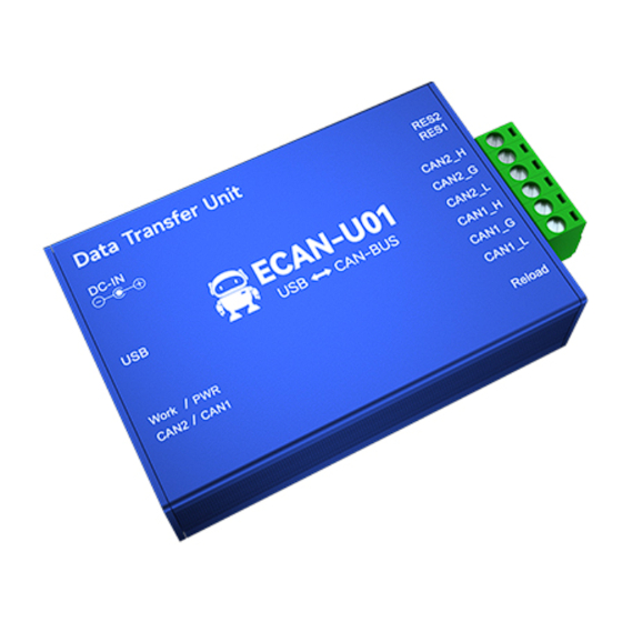
4. Interface definition & LED ECAN-U01 integrates 1 - way USB interface, one-way DC8-28V auxiliary power interface, one reset button, 2 - way standard CAN-bus interface and 2 - way 120 Ω matching resistance dial code. The CAN-bus interface is derived from a 6 - pin plug-in terminal, which can be used to connect two CAN - bus networks or devices with CAN-bus interfaces. -
Page 9: Technical Indicators
After the ECAN-U01 is powered on, the four indicators light up at the same time, and then the PWR and Work lights are always on , but the CAN1 and CAN2 lights are off, indicating that the device has been powered and the system has completed initialization;... -
Page 10: Equipment Usage
USB port. Connect the PC and ECAN-U01 directly through the supplied USB cable, and supply +5V power to ECAN-U01 from the USB cable . At this time, the indicators PWR and Work are on, indicating that the device is working normally and is in the state to be connected. -
Page 11: Can Bus Terminating Resistor
120Ω termination resistors. Note: ECAN-U01 has integrated 120Ω terminal resistance, you can choose whether to connect the resistance to the bus through the DIP switch, the DIP switch is next to the 6pin terminal, R1 , R2 correspond to the terminal resistance of CAN1 , CAN2 , dial to ON position to enable the resistor. -
Page 12: Pause Display Function
7.2. Pause display function Click Pause to pause the currently scrolling data window. The device and software can still receive data normally when paused, but the data window will not be refreshed. Click Continue to resume scrolling. Copyright ©2012–2022,Chengdu Ebyte Electronic Technology Co.,Ltd. -
Page 13: Display Mode
The data in the receive / transmit window and the data in the buffer area can be cleared. 7.5. Filter settings Receive filter settings can set filter ID/ time / channel number / length / data, etc. If filter is set, the software will Copyright ©2012–2022,Chengdu Ebyte Electronic Technology Co.,Ltd. -
Page 14: Bus Diagnostic Function
When a bus error occurs during the use of the device, the CAN1/CAN2 data light of the device will display a red constant light display, and the red alarm will not disappear until the bus returns to normal. And the host computer displays the number of error frames, as shown in the figure: Copyright ©2012–2022,Chengdu Ebyte Electronic Technology Co.,Ltd. -
Page 15: Data Transmission Mode
8.2. Send error frame count function The software can catch sending errors on the device, and when sending data fails, the count of error frames will be displayed at the bottom right of the software. As shown Copyright ©2012–2022,Chengdu Ebyte Electronic Technology Co.,Ltd. -
Page 16: Important Statement
ECAN-U01 User Manual 9. Important Statement Ebyte reserves the right of final interpretation and modification of all contents in this manual. Due to the continuous improvement of the hardware and software of the product, this manual may be changed without prior notice, and the latest version of the manual shall prevail.