Subscribe to Our Youtube Channel
Summary of Contents for LIXiSE R 448 V50
- Page 1 Armature Field 10 Yellow 11 Red 12 Black Green X1 Z2 E+ E- 0V 110 220 Slow fuse 250V 10 A with LAM without LAM Frequency 50Hz 60Hz R 448 LAM 13 % ST10...
- Page 2 R448 & R448 V50 A.V.R. This manual concerns the alternator A.V.R. which you have just purchased. We wish to draw your attention to the contents of this maintenance manual. By following certain important points during installation, use and servicing of your A.V.R., you can look forward to many years of trouble-free operation.
-
Page 3: Table Of Contents
R448 & R448 V50 A.V.R. CONTENTS 1 - GENERAL INFORMATION....................5 1.1 - Description........................5 1.2 - Identification........................2 - SUPPLY ..........................5 2.1 - AREP excitation system ....................5 2.2 - PMG excitation system ....................6 2.3 - SHUNT or separate excitation system.................7 3 - R448 A.V.R........................8 3.1 - Characteristics ......................8 3.2 - Frequency compared with voltage (without LAM)............8 3.3 - LAM (Load Acceptance Module) characteristics ............8... -
Page 4: General Information
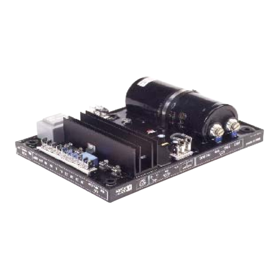
These 2 A.V.R.s have strictly identical 1.1 - Description characteristics dimensions, The A.V.R. R 448 V50 is delivered in a box following details distinguish the V50: designed to be mounted on a panel with - an adjuster dedicated to the alternator suspension. -
Page 5: Supply
R448 & R448 V50 A.V.R. The first winding has a voltage in proportion 2 - SUPPLY to that of the alternator (characteristic 2.1 - AREP excitation system Shunt), the second has a voltage in For both AREP & PMG excitation systems, proportion to the stator current (compound the alternator voltage regulator is the R characteristic: Booster effect). -
Page 6: Pmg Excitation System
R448 & R448 V50 A.V.R. jumper must be disconnected. 2.2 - PMG excitation system These two principles provide the machine With PMG excitation, a permanent magnet with a short-circuit current capacity of 3 IN generator (PMG) added to the alternator for 10 s, and good immunity to distortions supplies the AVR with voltage which is generated by the load. -
Page 7: Shunt Or Separate Excitation System
R448 & R448 V50 A.V.R. - 3-phase sensing (R 731 module) 2.3 - SHUNT or separate excitation - LAM function integrated in the R 448 AVR. system In SHUNT excitation, R 448 A.V.R. is In this case of LSA 42.2, A.V.R. and supplied by main windings (140V - 50/60 module(s) must be installed in the Hz) to X1, X2. -
Page 8: R448 A.v.r
R448 & R448 V50 A.V.R. Configuration jumpers function 3 - R448 A.V.R. 3.1.1 - 3.1 - Characteristics Delivrery config. Pot. Position Function - Shunt power supply: max 150V - 50/60 Hz Open Closed - Rated overload current: 10A - 10s Open for module 3-ph. -
Page 9: Frequency Compared With Voltage (Without Lam)
R448 & R448 V50 A.V.R. 3.2 - Frequency compared with Voltage voltage (without LAM) Underspeed and LAM ST5 disconnected Voltage Voltage Bend 57.5 Hz 48 Hz 100 % 50 Hz 0.85 U 60 Hz Frequency 50 Hz 60 Hz 48 or 57.5 Hz 50 or 60 Hz 3.3 - LAM (Load Acceptance Module) characteristics... -
Page 10: Typical Effects Of The Lam With A Diesel Engine With Or Without A Lam (U/F Only)
R448 & R448 V50 A.V.R. 3.4 - Typical effects of the LAM with 3.5 - R448 A.V.R. options a diesel engine with or without a - Current transformer for parallel operation of../ 1A Š 2.5 VA CL 1 (See the diagram (U/F only) in this manual). -
Page 11: Installation - Commissioning
R448 & R448 V50 A.V.R. a) Initial potentiometer settings (see table 4 - INSTALLATION - COMMISSIONING below) 4.1 - Electrical checks on the AVR - Remote voltage adjustment potentiometer - Check that all connections have been : centre (ST4 jumper removed). made properly as shown in the attached wiring diagram. - Page 12 R448 & R448 V50 A.V.R. the voltage between E+ and E- (approx. 10V 4.2.2 - Max. excitation setting (excitation D.C.). The best response times are obtained ceiling) at the limit of the instability. If no stable Max. excitation depending on the mains frequency position can be obtained, try disconnecting or replacing the ST2 jumper (normal/fast).
- Page 13 R448 & R448 V50 A.V.R. Open switch (D) : the excitation current The exciter is switched off by disconnecting should increase to its preset ceiling, remain the AVR power supply (1 wire on each at that level for ≥ 1 second in AREP or 10 auxiliary winding) - contact rating 16 A - seconds in PMG and then drop to <...
-
Page 14: Electrical Faults
R448 & R448 V50 A.V.R. 4.3 - Electrical faults Fault Action Effect Check/Cause The alternator builds up and its voltage is - Lack of residual magnetism still correct when the battery is removed. The alternator builds up but its voltage - Check the connection of the voltage reference to No voltage at Connect a new battery of 4... -
Page 15: Spare Parts
Code A.V.R. R 448 AEM 110 RE 016 A.V.R. R 448 V50 AEM 110 RE 022 5.2 - Technical support service Our technical support service will be happy to provide any information you require. When ordering spare parts, you should in-...


Need help?
Do you have a question about the R 448 V50 and is the answer not in the manual?
Questions and answers