Advertisement
Quick Links
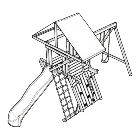
PB 5207
R R
PB 6207
Warning:
Do not allow children on the playset until
is has been completely built and properly anchored
ASSEMBLY INSTRUCTIONS
Swing•N•Slide • 1212 Barberry Drive • Janesville, Wisconsin 53545
Visit our web site at: www.swing-n-slide.com or call us at 1-800-888-1232
© Playcore Inc. 2012
Printed in USA
LA 7007
Advertisement

Subscribe to Our Youtube Channel
Related Manuals for Playcore Swing-N-Slide PB 5207


Summary of Contents for Playcore Swing-N-Slide PB 5207
- Page 1 Do not allow children on the playset until is has been completely built and properly anchored ASSEMBLY INSTRUCTIONS Swing•N•Slide • 1212 Barberry Drive • Janesville, Wisconsin 53545 Visit our web site at: www.swing-n-slide.com or call us at 1-800-888-1232 © Playcore Inc. 2012 Printed in USA LA 7007...
- Page 2 Safety Checklist for Swing-N-Slide Playsets & Accessories Save this instruction sheet in the event the manufacturer needs to be contacted. Observing the following statements and warnings reduces the likelihood of serious or fatal injury. Installation Safety – Have You: Consulted the assembly instructions supplied with your particular model? ...
- Page 3 This product is intended for single family home/residential use only and not intended for use in any public setting. Placement in any public setting constitutes a misuse of this product. IMPORTANT! Additional required safety installation instructions According to ASTM requirements, all kits must be anchored to the ground and if the unit has a climbing rope, the rope must be anchored to the ground. If soil conditions permit stakes to be pulled out easily, cementing into the ground is necessary.
- Page 4 DIMENSIONS MINIMUM USE ZONE FOR PLAY EQUIPMENT SHALL EXTEND NO LESS THAN 72” FROM ALL SIDES OF THE PLAY STRUCTURE. SWING USE ZONE EXTENDS NO LESS THAN 144”.
-
Page 5: Tools Required
TOOLS REQUIRED DRILL 1/2” & 9/16” SOCKET HAMMER ADJUSTABLE TAPE MEASURE & WRENCH WRENCH PHILLIPS BIT CARPENTER SAFETY GLASSES 1/8” DRILL BIT SQUARE INCLUDED HARDWARE 1-1/4” Lag Screw (x20) T-20 Bit (x1) 1/4-20 Weld Nut (x16) 2” Lag Screw (x72) 1/4”... - Page 6 INCLUDED HARDWARE NOTE: Included hardware is used for multiple kits and will result in extra parts. 5/16” Wood Loc Washer (x8) 3/8” Wood Loc Washer (x24)
-
Page 7: Included Components
INCLUDED COMPONENTS 4x4 Wrap Loc (x3) 4x4 Shelf Loc (x4) Angle Brace (x4) EZ Frame Bracket (x2) Beam Brace (x1) L Bracket (x4) Anchor It Strap (x6) Anchor It (x6) Quick Link (x6) Play Handle (x4) Bolt Cover (x3) Climbing Rock (x8) Steering Wheel w/ Hdw (x1) Super Speedwave Slide (x1) Cargo Net (x1) - Page 8 INCLUDED COMPONENTS Ring Trap (x1) XD Swing Seat (x2) Chain 33” (x2) Climbing Rope (x1) SA 2891 SA 2882 SA 2883 SA 2884 Rock Wall Panel (x2) Swing Beam Panel (x1) Deck Panel A (x2) Swing Beam Assembly (x1) ID Tag w/ Hdw (x1) Plan (x1) Tarp w/ Hdw (x1)
-
Page 9: Board List
BOARD LIST... - Page 10 USE THE CORRECT FASTENER Use the guides below to help select the correct length, quantity & location of screws for the board installation. Avoid splitting your lumber by offsetting your screws at least 3/4” from edge. All hardware should be driven until fl ush with the surface or no deeper than 1/16”. 2x4 to 4x4 &...
-
Page 11: Bracket Installation
BRACKET INSTALLATION Shelf-Loc bracket CORRECT INCORRECT Cup-Loc bracket CORRECT INCORRECT Bracket mounting 1. Always use lag screws 2. Brackets interlock with each other. NEVER position them in a non-interlocking position. 3. Place lag screws in brackets only where instructed. Do NOT fi ll in every hole as this will lead to a hardware shortage. - Page 12 STEP 1 2” Lag Screw (x8) PF 4517 4x4x51 39” Post A (2) 2” Lag Screws PF 4517 per bracket 4x4x51 39” Post B PF 4517 4x4x51 39” Post C (2) 2” Lag Screws per bracket 1. Attach brackets as shown. Note the hole orientation of the board.
- Page 13 STEP 2 PF 4516 4x4x18-3/8 Post A Post C Upright Support PF 4519 4x4x73-1/2 Upright Support A Support B 3/8” Loc Nut 3/8” Washer 3/8 Wood Loc Washer 3/8”-16 x 6” Carriage Bolt PF 4517 Post B 4x4x51 Support C Support D 1.
- Page 14 STEP 3 Support A Support B 5/16 Wood Loc Washer 5/16”-18 x 7” Carriage Bolt Support C Support D 1. Insert hardware into Upright(s) as shown. Note the post & bracket orientation.
- Page 15 STEP 4 Support B Support A Angle Brace HOLD FLUSH Support D Support C 2” Lag Screw (x24) 1. Slide Angle Brace over bolt and attach as shown. Note the post & bracket orientation.
- Page 16 STEP 5 Support A 3/8 Wood Loc Washer 3/8”-16 x 7 Carriage Bolt Support B 5/16” Washer & Loc Nut Frame 1 PF 4573 4x6x93-1/4 Joist 3/8” Loc 3/8” Washer 5/16” Washer & Loc Nut Check to make sure structure is square 1.
- Page 17 STEP 6 Support D 3/8 Wood Loc Washer 3/8”-16 x 7 Carriage Bolt Support C 5/16” Washer & Loc Nut Frame 2 PF 4573 4x6x93-1/4 Joist 3/8” Loc 3/8” Washer 5/16” Washer & Loc Nut Check to make sure structure is square 1.
- Page 18 STEP 7 2” Lag Screw (x24) 1. Attach Angle Brace to deck joist(s) as shown.
- Page 19 STEP 8 PF 4565 2x4x108 30” FLUSH 30” Frame 1 PF 4565 2x4x108 30” FLUSH Check to make sure 30” structure is square Frame 2 2-1/2” Deck Screw (x12) 1. Attach top board as shown. Note the post & bracket orientation.
- Page 20 STEP 9 18-3/8” OFFSET 1” FROM TOP OF DECK JOIST Angle Brace 1-1/4” Lag Screw (x8) 1. Attach L Bracket(s) to deck joist as shown on Frame 1 & Frame 2.
- Page 21 STEP 10 Check to make sure structure is square (2) PF 4566 2x6x34 FLUSH TOP SURFACES 1-1/4” Lag Screw (x12) 1. Attach boards as shown.
- Page 22 STEP 11 TIGHT TO BOTTOM OF JOIST (2) PF 4569 2x6x48 2-1/2” Deck Screw (x16) 1. Attach boards as shown.
- Page 23 STEP 12 Check to make sure structure is square 3/8” Washer 3/8”-16 x 5-1/2” Carriage Bolt 3/8” Loc Nut 3/8 Wood Loc PF 4568 Washer 2x6x48 Base 3/8” Washer 3/8”-16 x 7” Carriage Bolt 3/8” Loc Nut 3/8 Wood Loc Washer PF 4571 4x4x84...
- Page 24 STEP 13 (2) PF 4530 2x4x13” Ladder Support PF 4567 (2) PF 4532 2x6x41 2x4x15-13/16” Ladder Support FLUSH FLUSH Note: (4) 2-1/2” Deck Screw per board FLUSH ALL BOARDS ON BACK SIDE 2-1/2” Deck Screw (x48) 1. Attach Ladder Support(s) to Upright(s), then attach horizontal step to Ladder Supports as shown. 2.
- Page 25 STEP 14 1-5/8” PF 4567 2x6x41 2-1/2” Deck Screw (x4) 1. Attach board to unit as shown.
- Page 26 STEP 15 (2) PF 4501 2x4x18 Angle Support FLUSH BACKSIDE FLUSH 3-1/2 FLUSH 2-1/2” Deck Screw (x10) 1. Laminate boards and attach as shown.
- Page 27 STEP 16 48” FLUSH WITH POST TIP: Flex bracket(s) to make installation of 4x4 easier PF 4572 4x4x84 Accessory Arm Top 2” Lag Screw (x8) 1. Attach board as shown.
- Page 28 STEP 17 PF 4563 PF 4504 2x4x48 2x4x51 (3) 2-1/2” Deck (2) 2-1/2” Deck Screws per joint Screws per joint FLUSH FLUSH PF 4504 2x4x51 (2) 2-1/2” Deck Screws per joint Check to make sure structure is square 2-1/2” Deck Screw (x14) 1.
- Page 29 STEP 18 2-3/4” gap from post 1/2” gap 2-3/4” gap from post (2) SA 2883 Entry Deck Panel A 2-1/2” Deck Screw (x40) 1. Attach deck panel(s) as shown.
- Page 30 STEP 19 PF 4563 2x4x48 FLUSH (2) PF 4543 2x4x11-1/4 (4) 2-1/2” Deck Screws per board 45” 9” FLUSH (2) PF 4510 2x6x37 2-1/2” Deck Screw (x22) 1. Attach boards as shown.
- Page 31 STEP 20 SA 2882 Swing Beam Panel 45” 2-1/2” Deck Screw (x12) 1. Attach Swing Beam Panel as shown.
- Page 32 STEP 21 5/16”-18 x 3-1/2” Beam Brace Hex Head Bolt 5/16” Washer PF 4570 4x4x48 Swing Beam Support TIP: Flex bracket(s) to make 5/16” installation of 4x4 easier Washer 5/16” Loc Nut 2” Lag Screw (x8) FLUSH WITH POST 2-1/2” Deck Screw (x8) 1.
- Page 33 STEP 22 PF 4563 2x4x48 (2) 2-1/2” Deck Screws per joint PF 4504 PF 4508 2x4x51 2x4x85-1/2 FLUSH BOTTOM 53-3/4” EDGES 2-1/2” Deck Screw (x19) 1. Attach boards as shown.
- Page 34 STEP 23 EZ Frame Bracket 2-1/2” Deck Screw (x22) FLUSH EDGES (2) PF 4522 4x4x104 PF 4507 2x4x78 26-1/8” 102-1/4” 1. Attach EZ Frame bracket(s) to boards as shown. 2. Attach board as shown.
- Page 35 STEP 24 SA 2884 Swing Beam Assembly 5/16”-18 x 9” Carriage Bolt 5/16”-18 x 6” Carriage Bolt 5/16”-18 x 6” Carriage Bolt 5/16” Wood 7-1/8” Loc Washer 5/16” Wood 5/16” Loc Washer Washer 5/16” 4-3/8” Loc Nut 2-1/2” Deck 5/16” 5/16”...
- Page 36 STEP 25 5/16” gap typical PF 4513 2x6x58 (2) SA 2891 Rock Wall Panel 2-1/2” Deck Screw (x28) 1. Attach rock wall panels as shown.
- Page 37 STEP 26 1/4-20 T-Nut Climbing Rock Note: 1/4” Loc Maximum hardware Washer thickness is 1-1/2” 8mm Washer 1/4”-20 x 2-1/4 Hex Head Bolt 1. Mark locations of Climbing Rocks on rock wall and drill a 3/8” hole (Avoid rear supports). 2.
- Page 38 STEP 27 1” Rope Staple 1. Insert rope thru hole in top support board and tie an overhand knot. 2. Tie an overhand knot approximate every 18” for hand grips, for a total of 5 knots. 3. Pull bottom of rope under Rock Wall, attach one rope staple, fold back onto itself and attach 2nd staple.
- Page 39 STEP 28 5/16”-18 x 3” Carriage Bolt 5/16” Loc Nut 5/16” Washer Steering Wheel Spacer Note: If lumber is greater than 2” thick, you will need to counterbore the hole appropriately. 1. Choose location for the Steering Wheel and drill one 3/8” hole. 2.
- Page 40 STEP 29 5/16” Loc Nut 5/16” Washer Cargo Net 2” Deck Screws Bolt Cover 1/2” Rope 1/2” Rope Staple Staple 1. Insert eye bolt(s) into Accessory Arm Top and fasten as shown. 2. Attach Bolt Cover(s) over each eye bolt end as shown. 3.
- Page 41 STEP 30 1/4” Washer 1/4 x 1-3/4” Pan Screw 11” ABOVE DECK 1-3/4” Pan Screw (x8) 1. Mount Safety Handle(s) on posts as shown.
- Page 42 STEP 31 HOLD THE TARP END 1” FROM TOP OF BOARD Tarp Snap Screw (x10) 1. Wrap one end of the tarp around one support and tap the head of the snap(s) to leave an indent. 2. Install the Snap Screws at the indentations and attach the tarp to them. 3.
- Page 43 STEP 32 Tighten Quick Link(s) XD Swing Seat Quick Link Quick Link Quick Link “Open” “Closed” Note: For correct installation, the thread must be at the bottom 1. Attach Quick Link(s) to swing hangers as shown. 2. Attach XD Swing Seat(s) to Quick Link(s).
- Page 44 STEP 33 Tighten Quick Link(s) Ring Trap Quick Link Quick Link “Open” “Closed” Note: For correct installation, the thread must be at the bottom 1. Assemble Chain(s) to Ring Trap as shown. 2. Attach Chains(s) to swing hangers as shown.
- Page 45 STEP 34 1” Truss Screws 1-1/4” Deck Screws 2” Grade 1-1/4” Deck Screws PF 4526 2x4x15-3/4 Slide Stake 1” Truss Screw (x4) 1-1/4” Deck Screw (x2) 1. Attach slide as shown.
- Page 46 STEP 35 5/16” Washer Fold up 1-1/2” Lag Anchor-It Screw Strap Anchor-It 5/16 x 1-1/2” Lag Screw (x6) 1. Place swing set in fi nal location and mount Anchor-It(s) at locations circled above. 2. Twist the Anchor-It into the ground until only the loop is exposed. 3.
- Page 47 STEP 36 1/2” Pan Screw (x2) 1. Attach ID Tag as shown.
- Page 48 Weekend support available April through Labor Day Also available on Memorial Day, Fourth of July & Labor Day Technical Support from experienced Swing-N-Slide Customer Service Representatives who have actually built a swing set themselves. © Playcore Inc. 2012 Printed in USA...
Need help?
Do you have a question about the Swing-N-Slide PB 5207 and is the answer not in the manual?
Questions and answers