Gree GWH09QB-K6DNA5E Service Manual
Hide thumbs
Also See for GWH09QB-K6DNA5E:
- Service manual (220 pages) ,
- Service manual (161 pages) ,
- Service manual (201 pages)

Related Manuals for Gree GWH09QB-K6DNA5E


Summary of Contents for Gree GWH09QB-K6DNA5E
- Page 1 Change for life Service Manual Models: GWH09QB-K6DNA5E GWH09QB-K6DNB6E GWH09QB-K6DNC2E GWH09QB-K6DNA1E Models: GWH12QC-K6DNA1D GWH18QD-K6DNA1D (Refrigerant R32) GREE ELECTRIC APPLIANCES, INC. OF ZHUHAI...
-
Page 2: Table Of Contents
6. Function and Control ..................22 6.1 Remote Controller Introduction ..................22 6.2 GREE+ App Operation Manual ..................28 6.3 Ewpe Smart App Operation Manual ................. 29 6.4 Brief Description of Modes and Functions ................ 30 Part Ⅱ : Installation and Maintenance ........... - Page 3 Service Manual 9. Maintenance ......................... 45 9.1 Error Code List ........................45 9.2 Procedure of Troubleshooting ..................... 53 9.3 Troubleshooting for Normal Malfunction ................68 10. Exploded View and Parts List ..............70 10.1 Indoor Unit ......................... 70 10.2 Outdoor Unit ........................75 11.
-
Page 4: Part Ⅰ : Technical Information
Service Manual Part Ⅰ : Technical Information 1. Summary Indoor Unit GWH09QB-K6DNA1E/I GWH12QC-K6DNA1D/I GWH09QB-K6DNA5E/I GWH18QD-K6DNA1D/I GWH09QB-K6DNC2E/I GWH09QB-K6DNB6E/I Outdoor Unit GWH12QC-K6DNA1D/o GWH18QD-K6DNA1D/o GWH09QB-K6DNA1E/o Remote Controller YAC1FB9(WiFi) Technical Information... - Page 5 Product code Indoor model Outdoor model product code product code Controller GWH09QB-K6DNA1E CB419015801 GWH09QB-K6DNA1E/I CB419N15800 GWH09QB-K6DNA1E/O CB419W15801 GWH09QB-K6DNA5E CB425012501 GWH09QB-K6DNA5E/I CB425N12500 GWH09QB-K6DNA1E CB419015800 GWH09QB-K6DNA1E/I CB419N15800 GWH09QB-K6DNA5E CB425012500 GWH09QB-K6DNA5E/I CB425N12500 GWH09QB-K6DNA1E/O CB419W15800 GWH09QB-K6DNB6E CB435009600 GWH09QB-K6DNB6E/I CB435N09600 YAC1FB9 GWH09QB-K6DNC2E CB439013300 GWH09QB-K6DNC2E/I CB439N13300...
-
Page 6: Specifications
Service Manual 2. Specifications 2.1 Specification Sheet GWH09QB-K6DNA1E GWH09QB-K6DNA1E GWH09QB-K6DNA5E Model GWH09QB-K6DNB6E GWH09QB-K6DNA5E GWH09QB-K6DNC2E CB419015800 CB419015801 CB425012500 Product Code CB435009600 CB425012501 CB439013300 Rated Voltage 220-240 220-240 Power Rated Frequency Supply Phases Power Supply Mode Outdoor Outdoor Cooling Capacity(Min~Max) 2700(450~3500) 2700(450~3500) - Page 7 Service Manual Model of Outdoor Unit GWH09QB-K6DNA1E/o GWH09QB-K6DNA1E/o Product Code of Outdoor Unit CB419W15801 CB419W15800 ZHUHAI LANDA CoMPRESSoR ZHUHAI LANDA CoMPRESSoR Compressor Manufacturer/Trademark Co., LTD Co., LTD Compressor Model QXF-A079zE190A QXF-A079zE190A Compressor oil FW68DA FW68DA Compressor Type Rotary Rotary L.R.A. Compressor RLA Compressor Power Input Overload Protector...
- Page 8 Service Manual Parameter Unit Value Model GWH12QC-K6DNA1D Product Code CB419015501 CB419015500 Rated Voltage 220-240 220-240 Power Rated Frequency Supply Phases Power Supply Mode Outdoor Outdoor Cooling Capacity 3500 3500 Heating Capacity 3670 3670 Cooling Power Input 1085 1085 Heating Power Input Cooling Current Input Heating Current Input Rated Input...
- Page 9 Service Manual Outdoor Unit Model GWH12QC-K6DNA1D/o GWH12QC-K6DNA1D/o Outdoor Unit Product Code CB419W15501 CB419W15500 ZHUHAI LANDA ZHUHAI LANDA Compressor Manufacturer CoMPRESSoR Co.,LTD CoMPRESSoR Co.,LTD Compressor Model QXF-A102zE190B QXF-A102zE190B Compressor oil FW68DA FW68DA Compressor Type Rotary Rotary Compressor LRA. Compressor RLA Compressor Power Input 1023 1023 Compressor Overload Protector...
- Page 10 Service Manual Parameter Unit Value Model GWH18QD-K6DNA1D Product Code CB419015600 CB419015601 Rated Voltage 220-240 220-240 Power Rated Frequency Supply Phases Power Supply Mode Outdoor Outdoor Cooling Capacity 5200 5200 Heating Capacity 5300 5300 Cooling Power Input 1528 1528 Heating Power Input 1410 1410 Cooling Current Input...
- Page 11 Service Manual Outdoor Unit Model GWH18QD-K6DNA1D/o(LCLH) GWH18QD-K6DNA1D/o(LC) Outdoor Unit Product Code CB419W15600 CB419W15601 ZHUHAI LANDA CoMPRESSoR ZHUHAI LANDA CoMPRESSoR Compressor Manufacturer Co.,LTD Co.,LTD Compressor Model QXF-B141ZF030F QXF-B141ZF030F Compressor oil FW68DA or equivalent FW68DA or equivalent Compressor Type Rotary Rotary Compressor LRA. Compressor RLA Compressor Power Input 1410...
-
Page 12: Operation Characteristic Curve
Service Manual 2.2 Operation Characteristic Curve Cooling Heating Cooling Heating 220V Conditions 220V Indoor: DB27°C/WB19°C Outdoor: DB35°C/WB24°C Indoor air flow: High Pipe length: 5m 230V 230V 240V Conditions Indoor: DB20°C/WB15°C 240V Outdoor: DB7°C/WB6°C Indoor air flow: High Pipe length: 5m 10 20 30 40 50 60 70 80 90 100 Compressor speed (rps) Compressor speed (rps) -
Page 13: Cooling And Heating Data Sheet In Rated Frequency
Service Manual 2.4 Cooling and Heating Data Sheet in Rated Frequency Cooling: Pressure of gas pipe Inlet and outlet pipe Rated cooling Compressor connecting indoor and temperature of heat Fan speed of Fan speed of condition(°C) (DB/WB) Model revolution outdoor unit exchanger indoor unit outdoor unit... -
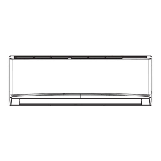
Page 14: Outline Dimension Diagram
Service Manual 3. Outline Dimension Diagram 3.1 Indoor Unit 123.5 179.5 168.5 159.5 Φ55 Φ55 Φ55 Φ55 124.7 83.2 Φ55 Φ55 Unit:mm Model Technical Information... -
Page 15: Outdoor Unit
Service Manual 3.2 Outdoor Unit Unit:mm Unit:mm Technical Information... - Page 16 Service Manual GWH09QB-K6DNA1E/o Unit:mm Technical Information...
-
Page 17: Refrigerant System Diagram
Service Manual 4. Refrigerant System Diagram 12/18K Cooling and heating model Indoor unit Outdoor unit Gas pipe side Valve 4-Way valve Di s charge Heat Suction Accumlator exchanger Compressor (evaporator) Heat exchanger Liquid pipe (condenser) side Valve Strainer Electric Strainer expand valve COOLING... -
Page 18: Electrical Part
Service Manual 5. Electrical Part 5.1 Wiring Diagram ● Instruction Symbol Symbol Color Symbol Symbol Color Symbol Name White Green Jumper cap Yellow Brown CoMP Compressor Blue Grounding wire YEGN Yellow/Green Black Violet orange Note: Jumper cap is used to determine fan speed and the swing angle of horizontal lover for this model. ●... - Page 19 Service Manual ● Outdoor Unit GWH09QB-K6DNA1E/o(CB419W15801) 600007000687 GWH09QB-K6DNA1E/o(CB419W15800) 60000700068702 These circuit diagrams are subject to change without notice, please refer to the one supplied with the unit. Technical Information...
- Page 20 Service Manual GWH12QC-K6DNA1D/o(LC)(CB419W15501) 60000700111002 GWH12QC-K6DNA1D/o(LCLH) (CB419W15500) 60000700111001 Technical Information...
- Page 21 Service Manual GWH18QD-K6DNA1D/o(CB419W15601) 63610000218 GWH18QD-K6DNA1D/o(CB419W15600) 6361000021801 These circuit diagrams are subject to change without notice, please refer to the one supplied with the unit. Technical Information...
-
Page 22: Pcb Printed Diagram
Service Manual 5.2 PCB Printed Diagram Indoor Unit Top view Name Interface of communication wire for indoor unit and outdoor unit Interface of live wire Fuse Interface of health function neutral wire Interface of neutral wire Interface of fan Interface of health function live wire 8 Auto button 9 Up&down swing interface Interface of PG feedback... - Page 23 Service Manual Outdoor Unit ● Top view Name 1 Interface of compressor wire 2 Interface of reactor Terminal of chassis electric heater Terminal of compressor electric heater 5 Terminal of 4-way valve 6 Interface of outdoor fan 7 Interface of earthing wire 8 Communication interface 9 Interface of netural wire 10 Interface of live wire...
- Page 24 Service Manual ● Top view Name Compressor three phase input interface Terminal of system high pressure protection Compressor overload protection terminal 4 Interface of temperature sensor Terminal of electronic expansion valve Terminal for low pressure protection Interface of fan 4-way valve terminal 2-way valve terminal Terminal of compressor electric heater Terminal of chassis electric heater...
-
Page 25: Function And Control
Service Manual 6. Function and Control 6.1 Remote Controller Introduction ON/OFF button MODE button FAN button TURBO button ▲/ button button button SLEEP button I FEEL button TIMER ON / TIMER OFF button CLOCK button QUIET button WiFi button LIGHT button button TEMP button Set fan speed... - Page 26 Service Manual Press this button to turn on the unit. Press this button again to turn off the unit. (This indicator is not available for some models). (This indicator is not available for some models). Operation indicator is ON. (This indicator is not available for some models).
- Page 27 Service Manual function is only available for some mode Press this button, can select Sleep 1 ( ), Sleep 2 ( ), Sleep 3 ( ) and cancel the Sleep, circulate between these, after electrified, Sleep Cancel is defaulted.Sleep 1 is Sleep mode 1, in Cool modes; sleep status after run for one hour, the main unit setting temperature will increase 1 , two hours, setting temperature increased 2 , then the unit will run at this setting temperature;...
- Page 28 Service Manual The Quiet function can be set up in all modes; Under the Quiet mode,the fan speed is not available. The Quiet function is only available for some models. When quiet function is selected Under cooling mode: indoor fan operates at notch 4 speed. 10 minutes later or when indoor ambient temperature≤28℃, indoor fan will operate at notch 2 speed or quiet mode according to the comparison between indoor ambinet temperature and set temperature.
- Page 29 Service Manual Technical Information...
- Page 30 Service Manual Technical Information...
-
Page 31: Gree+ App Operation Manual
GREE+ App Download Linkage Scan the QR code or search "GREE+" in the application market to download and install it. When "GREE+" App is installed, register the account and add the device to achieve long-distance control and LAN control of Gree smart home appliances. -
Page 32: Ewpe Smart App Operation Manual
Service Manual 6.3 Ewpe Smart App Operation Manual Control Flow Chart Internet Cloud intelligent Cellular/ Home Wi-Fi home Other Wi-FI appliances Home wireless router Home Wi-Fi Operating Systems Requirement for User's smart phone: iOS system Android system Support iOS7.0 and Support Android 4.4 and above version above version... -
Page 33: Brief Description Of Modes And Functions
Service Manual 6.4 Brief Description of Modes and Functions Indoor Unit ● 1.Basic function of system (1)Cooling mode (1) Under this mode, fan and swing operates at setting status. Temperature setting range is 16~30 (2) During malfunction of outdoor unit or the unit is stopped because of protection, indoor unit keeps original operation status. (2)Drying mode (1) Under this mode, fan operates at low speed and swing operates at setting status. - Page 34 Service Manual (8)I feel control mode After controller received I feel control signal and ambient temperature sent by remote controller, controller will work according to the ambient temperature sent by remote controller. (9)Entry condition for compulsory defrosting function When turn on the unit under heating ode and set temperature is 16 C (or 16.5 C by remote controller), press “+, -, +, -, +, -”...
- Page 35 Service Manual Outdoor Unit ● 1. Cooling mode: Working condition and process of cooling mode: ① When Tindoor ambient temperature≥Tpreset, unit enters into cooling mode. Indoor fan, outdoor fan and compressor start operation. Indoor fan operates according to set fan speed. ②...
- Page 36 Service Manual Auto mode is determined by controller of IDU. See IDU logic for details. 8. 8 C heating Set temperature is 8 C. Display board of IDU displays 8 C. Under this mode, “Cold air prevention” function is shielded. If compressor is operating under this mode, fan speed will adjust according to auto fan speed;...
-
Page 37: Part Ⅱ : Installation And Maintenance
Service Manual Part Ⅱ : Installation and Maintenance 7. Notes for Installation and Maintenance Safety Precautions: 10. If the power cord or connection wire is not long enough, please get the specialized power cord or connection wire Important! from the manufacture or distributor. Prohibit prolong the wire by yourself. - Page 38 Service Manual Safety Precautions for Installing and Relocating the Unit: To ensure safety, please be mindful of the following precautions. Warnings 1. When installing or relocating the unit, be sure to keep the refrigerant circuit free from air or substances other than the specified refrigerant.
- Page 39 Service Manual Safety Operation of Flammable Refrigerant Qualification requirement for installation and maintenance man ●All the work men who are engaging in the refrigeration system should bear the valid certification awarded by the authoritative organization and the qualification for dealing with the refrigeration system recognized by this industry. If it needs other technician to maintain and repair the appliance, they should be supervised by the person who bears the qualification for using the flammable refrigerant.
- Page 40 Service Manual Main Tools for Installation and Maintenance 1. Level meter, measuring tape 2. Screw driver 3. Impact drill, drill head, electric drill 4. Electroprobe 5. Universal meter 6. Torque wrench, open-end wrench, inner hexagon spanner 7. Electronic leakage detector 8.
-
Page 41: Installation
Service Manual 8. Installation 8.1 Installation Dimension Diagram Space to the wall Space to the wall At least 15cm At least 15cm Drainage pipe Installation and Maintenance... - Page 42 Service Manual Start installation Preparation before installation Read the requirements select installation Prepare tools for electric connection location Select indoor unit Select outdoor unit installation location installation location Install the support of outdoor unit Install wall-mounting (select it according to the actual situation) frame, drill wall holes Connect pipes of indoor Fix outdoor unit...
-
Page 43: Installation Parts-Checking
Service Manual 8.4 Requirements for electric connection 8.2 Installation Parts-checking 1. Safety Precaution Name Name (1) Must follow the electric safety regulations when installing Indoor unit Sealing gum the unit. Outdoor unit Wrapping tape (2) According to the local safety regulations, use qualified Support of outdoor power supply circuit and air switch. -
Page 44: Installation Of Indoor Unit
Service Manual 8.5 Installation of Indoor Unit 1. Choosing Installation Iocation Recommend the installation location to the client and then confirm it with the client. 2. Install Wall-mounting Frame Rear left (1) Hang the wall-mounting frame on the wall; adjust it in horizontal position with the level meter and then point out the Fig.3 Right... - Page 45 Service Manual (4) Put wiring cover back and then tighten the screw. Drain hose (5) Close the panel. Outlet pipe Note: (1) All wires of indoor unit and outdoor unit should be Tape connected by a professional. Drain hose Outlet Fig.9 pipe (2) If the length of power connection wire is insufficient, please...
-
Page 46: Installation Of Outdoor Unit
Service Manual 4. Connect Indoor and Outdoor Pipes Outdoor Indoor Fig.17 (1) Remove the screw on the right handle of outdoor unit and Wall pipe Sealing gum then remove the handle.(As show in Fig.21) Upper hook (2) Remove the screw cap of valve and aim the pipe joint at the bellmouth of pipe.(As show in Fig.22) Liquid pipe Pipe joint... -
Page 47: Vacuum Pumping And Leak Detection
Service Manual 2. Leakage Detection (1) With leakage detector: The drain hos can't raise Check if there is leakage with leakage detector. upwards (2) With soap water: If leakage detector is not available, please use soap water for Wall leakage detection. Apply soap water at the suspected position and keep the soap water for more than 3min. -
Page 48: Maintenance
Service Manual 9. Maintenance 9.1 Error Code List Display Method of Indoor Unit Indicator Display (during blinking, ON 0.5s and OFF Dual-8 Malfunction A/C status Possible Causes 0.5s) Code Name Display operation Cool Heating Indicator Indicator Indicator Possible reasons: During cooling and drying High 1. - Page 49 Service Manual Display Method of Indoor Unit Indicator Display (during blinking, ON 0.5s and OFF Dual-8 Malfunction A/C status Possible Causes 0.5s) Name Code operation Cool Heating Display Indicator Indicator Indicator When the outdoor unit receive signal of Gathering Gathering refrigerant ,the system will Nominal cooling mode refrigerant be forced to run under cooling mode for...
- Page 50 Service Manual Display Method of Indoor Unit Indicator Display (during blinking, ON 0.5s and OFF Dual-8 Malfunction A/C status Possible Causes 0.5s) Code Name operation Cool Heating Display Indicator Indicator Indicator Decrease Overload or temperature is too high; frequency All loads operate normally, while Refrigerant is insufficient;...
- Page 51 Service Manual Display Method of Indoor Unit Indicator Display (during blinking, ON 0.5s and OFF Dual-8 Malfunction A/C status Possible Causes 0.5s) Code Name operation Cool Heating Display Indicator Indicator Indicator Compressor intermediate Showing during middle cooling or middle frequence in heating test test state Overcurrent...
- Page 52 Service Manual Display Method of Indoor Unit Indicator Display (during blinking, ON 0.5s and OFF Dual-8 Malfunction A/C status Possible Causes 0.5s) Code Name operation Cool Heating Display Indicator Indicator Indicator 1. Bad contact of DC motor feedback terminal. 2. Bad contact of DC motor Internal fan motor, external fan motor, Internal motor control end.
- Page 53 Service Manual Display Method of Indoor Unit Indicator Display (during blinking, ON 0.5s and OFF Dual-8 Malfunction A/C status Possible Causes 0.5s) Code Name operation Cool Heating Display Indicator Indicator Indicator During cooling and drying Malfunction operation, the compressor will Theres circuit malfunction on outdoor units of complete stop while indoor fan will operate;...
- Page 54 Service Manual If malfunction occurs,corresponding code will display and the unit will resume normal until protection or malfunction disappears. Installation and Maintenance...
- Page 55 Service Manual Analysis or processing of some of the malfunction display: 1. Compressor discharge protection Possible causes: shortage of refrigerant; blockage of air filter; poor ventilation or air flow short pass for condenser; the system has noncondensing gas (such as air, water etc.); blockage of capillary assy (including filter); leakage inside four-way valve causes incorrect operation;...
-
Page 56: Procedure Of Troubleshooting
Service Manual 9.2 Procedure of Troubleshooting Indoor unit (1) Malfunction of Temperature Sensor F1, F2 Main detection points: ● Is the wiring terminal between the temperature sensor and the controller loosened or poorly contacted? ● Is there short circuit due to trip-over of the parts? ●... - Page 57 Service Manual (2) Malfunction of Blocked Protection of IDU Fan Motor H6 Main detection points: ● SmoothlyIs the control terminal of PG motor connected tightly? ● SmoothlyIs the feedback interface of PG motor connected tightly? ● The fan motor cant operate? ●...
- Page 58 Service Manual (3) Malfunction of Protection of Jumper Cap C5 Main detection points: ● Is there jumper cap on the mainboard? ● Is the jumper cap inserted correctly and tightly? ● The jumper is broken? ● The motor is broken? ●...
- Page 59 Service Manual (4) Malfunction of Zero-crossing Inspection Circuit Malfunction of the IDU Fan Motor U8 Main detection points: ● Instant energization afte de-energization while the capacitordischarges slowly? ● The zero-cross detectioncircuit of the mainboard is defined abnormal? Malfunction diagnosis process: Start Turn power off for 1minute,the turn...
- Page 60 Service Manual (5) Malfunction of detecting plate(WIFI) JF Start check if the connection wire are correctly connected detecting Replace the plate with the same model Is malfunction eliminated Replace the mainboard with the same model The end Installation and Maintenance...
- Page 61 Service Manual Outdoor unit: (1) Capacitor charge fault (Fault with outdoor unit) (AP1 below refers to the outdoor control panel) Main Check Points: ●Use AC voltmeter to check if the voltage between terminal L and N on the wiring board is within 210VAC~240VAC. ●Is the reactor (L) correctly connected? Is the connection loose or fallen? Is the reactor (L) damaged? Fault diagnosis process: Turn on the unit...
- Page 62 Service Manual (2) IPM Protection, Out-of-step Fault, Compressor Phase Overcurrent (AP1 below refers to the outdoor control panel) Main check points: ●Is the connection between control panel AP1 and compressor COMP secure? Loose? Is the connection in correct order? ●Is the voltage input of the machine within normal range? (Use AC voltmeter to measure the voltage between terminal L and N on the wiring board XT) ●Is the compressor coil resistance normal? Is the insulation of compressor coil against the copper tube in good condition? ●Is the working load of the machine too high? Is the radiation good?
- Page 63 Service Manual Energize and switch on Use AC voltmeter If the voltage Check the supply to measure the IPM protection between terminal L voltage and voltage between occurs after the and N on wiring machine has run for terminal L and N restore it to board XT is within a period of time?
- Page 64 Service Manual (3) High temperature and overload protection diagnosis (AP1 hereinafter refers to the control board of the outdoor unit) Mainly detect: ●Is outdoor ambient temperature in normal range? ●Are the outdoor and indoor fans operating normally? ●Is the heat dissipation environment inside and outside the unit good? Fault diagnosis process: Overheat and high temperature protection...
- Page 65 Service Manual (4) Start-up failure (following AP1 for outdoor unit control board) Mainly detect: ●Whether the compressor wiring is connected correct? ●Is compressor broken? ●Is time for compressor stopping enough? Fault diagnosis process: Power on the unit Restart it up after Is stop time of the compressor 3 minutes longer than 3 minutes?
- Page 66 Service Manual (5) Out of step diagnosis for the compressor (AP1 hereinafter refers to the control board of the outdoor unit) Mainly detect: ●Is the system pressure too high? ●Is the input voltage too low? Fault diagnosis process: Out of step occurs in Out of step occurs once the operation unit is powered on.
- Page 67 Service Manual (6) Overload and air exhaust malfunction diagnosis (following AP1 for outdoor unit control board) Mainly detect: ●Is the PMV connected well or not? Is PMV damaged? ●Is refrigerant leaked? Fault diagnosis process: 20 minutes after the complete unit is powered off Is the terminal FA for the Connect the...
- Page 68 Service Manual (7) Power factor correct or (PFC) fault (a fault of outdoor unit) (AP1 hereinafter refers to the control board of the outdoor unit) Mainly detect: ●Check if the reactor (L) of the outdoor unit and the PFC capacitor are broken Fault diagnosis process: Start Check wiring of the...
- Page 69 Service Manual (8) Communication malfunction: (following AP1 for outdoor unit control board) Mainly detect: ●Is there any damage for the indoor unit mainboard communication circuit? Is communication circuit damaged? ●Detect the indoor and outdoor units connection wire and indoor and outdoor units inside wiring is connect well or not, if is there any damage? Fault diagnosis process: Start...
- Page 70 Service Manual (9) Malfunction of Overcurrent Protection Main detection points: ● Is the supply voltage unstable with big fluctuation? ● Is the supply voltage too low with overload? ● Hardware trouble? Malfunction diagnosis process: Start Normal fluctuation should be within 10 % Is malfunction Is the supply voltage unstable of the rated voltage on the nameplate...
-
Page 71: Troubleshooting For Normal Malfunction
Service Manual 9.3 Troubleshooting for Normal Malfunction 1. Air Conditioner Cant be Started Up Possible Causes Discriminating Method (Air conditioner Status) Troubleshooting Confirm whether its due to power failure. If yes, No power supply, or poor After energization, operation indicator isnt bright wait for power recovery. - Page 72 Service Manual 4. ODU Fan Motor Cant Operate Possible causes Discriminating method (air conditioner status) Troubleshooting Connect wires according to wiring diagram to Wrong wire connection, or poor Check the wiring status according to circuit make sure all wiring terminals are connected connection diagram firmly...
-
Page 73: Exploded View And Parts List
Service Manual 10. Exploded View and Parts List 10.1 Indoor Unit 09/12K The component picture is only for reference; please refer to the actual product. Installation and Maintenance... - Page 74 Service Manual Part Code Description GWH12QC-K6DNA1D/I GWH09QB-K6DNB6E/I GWH09QB-K6DNC2E/I Product Code CB419N15500 CB435N09600 CB439N13300 Front Panel 20022475 20000300050T 20000300068S Display Board 30565231 30565281 30565281 Front Case Assy 20022489 00000200040 00000200040 Guide Louver 10512492 1051276301 1051276301 Air Louver (left) 10512725 10512720 10512720 Swing Lever 10582459 10582460...
- Page 75 Service Manual Part Code Description GWH09QB-K6DNA1E/I GWH09QB-K6DNA5E/I Product Code CB419N15800 CB425N12500 Front Panel Assy 20022496 00000300036 Display Board 30565231 30565260 Front Case Assy 20022495 2002249501 Guide Louver 10512722 1051272202 Air Louver 2 10512720 10512720 Swing Lever 10582460 10582460 Helicoid Tongue...
- Page 76 Service Manual The component picture is only for reference; please refer to the actual product. Installation and Maintenance...
- Page 77 Service Manual Part Code Description GWH18QD-K6DNA1D/I Product Code CB419N15600 Decorative Strip 20192613 Front Panel Assy 20022490 Display Board 30565233 Filter Sub-Assy 1112208906 Decorative Board (Left) 20192612 Front Case 20022484 Guide Louver 10512734 Axile Bush 10542036 Air Louver 1 10512733 Helicoid tongue 26112512 Left Axile Bush 10512037...
-
Page 78: Outdoor Unit
Service Manual 10.2 Outdoor Unit The component picture is only for reference; please refer to the actual product. Installation and Maintenance... - Page 79 Service Manual Part Code Description GWH09QB-K6DNA1E/o Product Code CB419W15800 CB419W15801 Electric Box Assy 100002061319 100002061410 Electric Box 20113034 20113034 Main Board 300027060176 300027060177 Reactor 43130184 43130184 Terminal Board 422000060016 422000060016 Wire Clamp 71010103 71010103 Front Grill 22413049 22413049 Front Panel 01533034P 01533034P Axial Flow Fan...
- Page 80 Service Manual 21 22 23 24 25 The component picture is only for reference; please refer to the actual product. Installation and Maintenance...
- Page 81 Service Manual Part Code Description GWH12QC-K6DNA1D/o (LCLH) GWH12QC-K6DNA1D/o(LC) Product Code CB419W15500 CB419W15501 Left Side Plate 01303200P 01303200P Fan Motor 1501308511 1501308511 Motor Support 01703136 01703136 Condenser Assy 011002060182 011002060182 Top Cover Sub-Assy 000051060003 000051060003 Rear Grill 01475014 01475014 Clapboard Sub-Assy 01233180 01233180 Compressor and Fittings...
- Page 82 Service Manual The component picture is only for reference; please refer to the actual product. Installation and Maintenance...
- Page 83 Service Manual Part Code Description GWH18QD-K6DNA1D/o Product Code CB419W15600 CB419W15601 Front Grill 22413045 22413045 Front Panel 01535013P 01535013P Drainage Connecter 06123401 06123401 Chassis Sub-assy 02803270P 02803270P Drainage Joint 06813401 06813401 Compressor and Fittings 009001060006 009001060006 Magnet Coil 4300876704 4300876704 4-Way Valve Assy 030152060089 030152060089 Cut off Valve Assy...
-
Page 84: Removal Procedure
Service Manual 11. Removal Procedure Caution: discharge the refrigerant completely before removal. 11.1 Removal Procedure of Indoor Unit 09/12K Note:Take A1 Panel for example. Step Procedure 1. Remove filter assembly Front panel Open the front panel. Push the left filter and right filter until they are separate from the groove on the front panel. - Page 85 Service Manual Step Procedure 4. Remove detecting plate(wifi) and electric box cover2 Remove the screws fixing detecting plate and remove detecting plate(wifi). Detecting plate(WIFI) Remove the screws fixing electric box cober2 and remove electric box2. 5. Remove front case sub-assy Screws Remove the screws fixing front case.
- Page 86 Service Manual Step Procedure 7. Remove electric box assy Screw Loosen the connection clasps between shield cover of electric box sub-assy and Clasps electric box, and then remove the shield cover of electric box sub-assy. Remove the screw fixing electric box assy . Electric box Shield cover of electric box sub-assy...
- Page 87 Service Manual Step Procedure Instruction: Some wiring terminal of this product is with lock catch and other devices. circlip The pulling method is as below: holder 1.Remove the soft sheath for some terminals at first, hold the circlip and then pull out the terminals.
- Page 88 Service Manual Step Procedure 9. Remove motor and cross flow blade Remove the screws fixing motor clamp Screws and then remove the motor clamp. Motor clamp Cross flow Remove the screws at the connection Screw Motor place of cross flow blade and motor; lift Holder the motor and cross flow blade upwards sub-assy...
- Page 89 Service Manual 1.Remove fifter assy Front panel Open the front panel. Push the left and rightfilters to make them break away from thegroove on the front case. Then remove the leftand right filters one by one. Left filter Front Right filter Groove case 2.Remove horizontal louver...
- Page 90 Service Manual 4.Remove electric box cover 2 Remove the screws on the electric box cover 2 and detecting plate(WIFI), then remove the electric box cover 2 and detecting plate(WIFI). Electric box cover2 Screw Note:The position of detection Detecting plate(WIFI) Electric box cover board(WIFI) may be different for different models.
- Page 91 Service Manual Step Procedure 7.Remove vertical louver Loosen the connection clasps between vertical louver and bottom case to remove vertion louver. Swing motor Screw off the screws that are locking the swing motor and take the motor off. 8.Remove electric box assy Loosen the connection clasps between shield cover of electric box sub-assy and electric box,and then remove the shield...
- Page 92 Service Manual Step Procedure Rotate the electric box assy. Twist off the screws Rotate the electric box assy. Twist offthe that are locking the wire clip and loosen the Screws screwsthat are locking the wire clip and power cord. Remove the wiring terminal of loosen the power cord.
- Page 93 Service Manual Step Procedure Adjust the position of conncetion pipe on evaporator up wards to remove it. 10.Remove motor and cross flow blade Remove the screws fixing motor clamp and then remove the motor clamp. ① Remove the screws at the connection place of cross flow blade and motor;...
-
Page 94: Removal Procedure Of Outdoor Unit
Service Manual 11.2 Removal Procedure of Outdoor Unit Step Procedure 1. Remove big handle Right side plate Remove the screw fixing big handle; slide out the big handle upwards to make the clasp of big handle separate from the groove of right side plate, and then remove the big handle. - Page 95 Service Manual Procedure Step 4. Remove the front cover Screws Screw off the screws that are locking the front cover. Then take it off. Screws Screws Front cover Screws 5. Remove axial flow blade Remove the nut fixing axial flow blade and then remove the axial flow blade.
- Page 96 Service Manual Step Procedure 6. Remove protective grille and right side plate Protective Remove the screws 1 fixing protective grille and then remove the protective grille grille. Screws 2 Screws 1 Right side plate Right side plate Remove the screws 2 fixing right side plate and then remove the right side plate.
- Page 97 Service Manual Step Procedure 8. Remove 4-way valve assy Unsolder the spot weld of 4-way valve assy, compressor and condenser, and then remove the 4-way valve assy . 4-way valve assy Note: When unsoldering the spot weld, wrap the 4-way valve with wet cloth completely to avoid damaging the valve due to high temperature.
- Page 98 Service Manual Step Procedure Clapboard 11. Remove clapboard sub-assy Loosen the screws of the Clapboard Sub- Assy . The Clapboard Sub-Assy has a hook on thelower side. Lift and pull the Clapboard Sub- Assyto remove. 12. Remove Compressor Remove the 2 screws fixing the gas valve. Unsolder the welding spot connecting gas valveand air return pipe and remove the gas valve.(Note: it is necessary to warp the gas...
- Page 99 Service Manual Steps Procedure 1.Remove big handle Before disassamble. Remove the screws fixing handle、valve big handle cover and then remove them. valve cover 2. Remove top cover top cover Remove the screws fixing top panel and then remove the top panel. Installation and Maintenance...
- Page 100 Service Manual Step Procedure 3.Remove grille 、protective grille and front panel Remove connection screws between the front grille and the front panel. Then remove the front grille. Remove connection screws connecting the front protective panel with the chassis and the motor support, and grille then remove the front panel.
- Page 101 Service Manual Step Procedure 6.Remove motor and motor support Remove the screws fixing motor and then remove the motor. Remove the screws fixing motor support and then remove the motor support. motor support motor 7.Remove electric box assy Remove the screws fixing electric box assy; cut off electric box assy the tieline;...
- Page 102 Service Manual Step Procedure 9.Remove 4-way valve assy and capillary sub-assy Unsolder the welding joints connecting the 4-way valve assy with capillary sub-assy, compressor and condenser; remove the 4-way valve. 4-way valve assy Note: Before unsoldering the welding joint, wrap the 4-way Capillary valve with a wet cloth completely to avoid damage Electronic...
- Page 103 Service Manual Steps Procedure 1. Remove top panel Twist off the screws used for fixing the handle and v alve cover , pull the handle and v alve cover up ward to remove it. handle valve top panel Remove the 3 screws connecting the top panel with the front panel and the right side plate, and then remove the top panel.
- Page 104 Service Manual Steps Procedure Remove the screws connecting the outer case with motor support, isolation plate and chassis; lift the outer case upwards; loosen the clasps of outer case with right side plate and left side plate, and then remove the outer case. outer case 3.
- Page 105 Service Manual Steps Procedure 4. Remove axial flow blade Remove the nut fixing axial flow blade and then remove the blade. axial flow fan motor support Remove the 6 screws fixing the motor and then remove the motor. Remove the 2 screws connecting the motor support and chassis, and then loosen the stopper to remove the motor support.
- Page 106 Service Manual Steps Procedure 6. Remove the soundproof sponge Tear off the sticking stripe and then remove the soundproof sponge. soundproof sponge 7. Remove isolation plate Remove the 2 screws connecting the isolation plate and condenser side plate; remove the 3 screws connecting the isolation plate and chassis, and then remove the isolation plate.
- Page 107 Service Manual Steps Procedure 9. Remove compressor compressor Remove the 3 foot nuts fixing compressor and then lift the compressor upwards to remove the compressor and damping cushion. Note: Keep the ports of discharge pipe and suction pipe from foreign objects. condenser sub-assy 10.
-
Page 108: Appendix
Service Manual Appendix: Appendix 1: Reference Sheet of Celsius and Fahrenheit Conversion formula for Fahrenheit degree and Celsius degree: Tf=Tcx1.8+32 Set temperature Fahrenheit Fahrenheit Fahrenheit display Fahrenheit display Fahrenheit display Fahrenheit Celsius (℃) Celsius (℃) Celsius (℃) temperature temperature temperature (℉)... -
Page 109: Appendix 3: Pipe Expanding Method
Service Manual Appendix 3: Pipe Expanding Method Pipe Note: Pipe cutter Improper pipe expanding is the main cause of refrigerant leakage.Please expand the pipe according to the following steps: Leaning Uneven Burr A:Cut the pip ● Confirm the pipe length according to the distance of indoor unit and outdoor unit. ●... -
Page 110: Appendix 4: List Of Resistance For Temperature Sensor
Service Manual Appendix 4: List of Resistance for Temperature Sensor Resistance Table of Ambient Temperature Sensor for Indoor and Outdoor (15K) Temp( C) Resistance(kΩ) Temp( C) Resistance(kΩ) Temp( Resistance(kΩ) Temp( Resistance(kΩ) 138.1 18.75 3.848 1.071 128.6 17.93 3.711 1.039 121.6 17.14 3.579 1.009... - Page 111 Service Manual Resistance Table of Tube Temperature Sensors for Indoor and Outdoor (20K) Temp( C) Resistance(kΩ) Temp( C) Resistance(kΩ) Temp( Resistance(kΩ) Temp( Resistance(kΩ) 181.4 25.01 5.13 1.427 171.4 23.9 4.948 1.386 162.1 22.85 4.773 1.346 153.3 21.85 4.605 1.307 20.9 4.443 1.269 137.2...
- Page 112 Service Manual Resistance Table of Discharge Temperature Sensor for Outdoor (50K) Temp( C) Resistance(kΩ) Temp( Resistance(kΩ) Temp( C) Resistance(kΩ) Temp( Resistance(kΩ) 853.5 18.34 4.75 799.8 93.42 17.65 4.61 89.07 16.99 4.47 703.8 84.95 16.36 4.33 660.8 81.05 15.75 4.20 620.8 77.35 15.17 4.08...
- Page 113 Add: West Jinji Rd, Qianshan, Zhuhai,Guangdong, China, 519070 Tel: (+86-756) 8522218 Fax: (+86-756) 8669426 E-mail: gree@gree.com.cn www.gree.com HONG KONG GREE ELECTRIC APPLIANCES SALES LIMITED Add: Unit 2612,26/F.,Miramar Tower 132 Nathan Road,TST,Kowloon,HK Tel: (852) 31658898 Fax: (852) 31651029 For product improvement, specifications and appearance in this manual are subject to change without prior notice.
Need help?
Do you have a question about the GWH09QB-K6DNA5E and is the answer not in the manual?
Questions and answers