Table of Contents
Advertisement
Change for Life
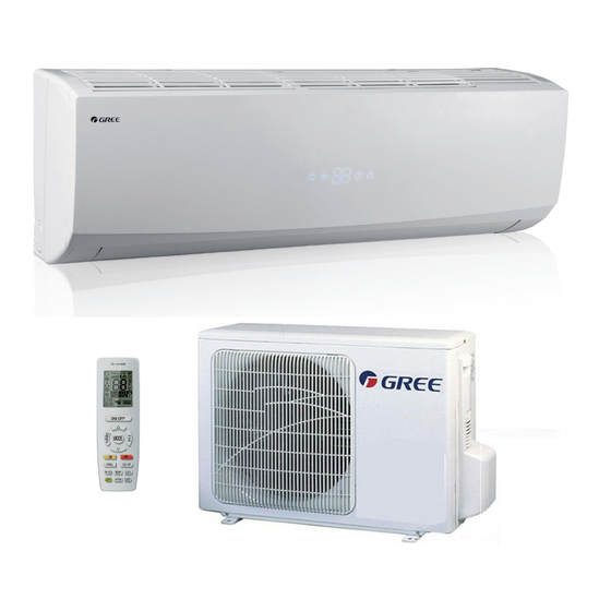
Service Manual
Models: GWH09QB-K3DNA1G
GWH09QB-K3DNA5G
GWH09QB-K3DNA5G
GWH09QB-K3DNB2G
GWH09QB-K3DNB4G
GWH09QB-K3DNB6G
GWH09QB-K3DNC2G
GWH09QB-K3DNC4G
GWH12QC-K3DNA1G
GWH12QC-K3DNA5G
GREE ELECTRIC APPLIANCES,INC.OF ZHUHAI
GWH12QC-K3DNB2G
GWH12QC-K3DNB4G
GWH12QC-K3DNB6G
GWH12QC-K3DNC2G
GWH12QC-K3DNC4G
(Refrigerant R410A)
Advertisement
Table of Contents
Troubleshooting


Need help?
Do you have a question about the GWH09QB-K3DNC2G and is the answer not in the manual?
Questions and answers