Table of Contents
Advertisement
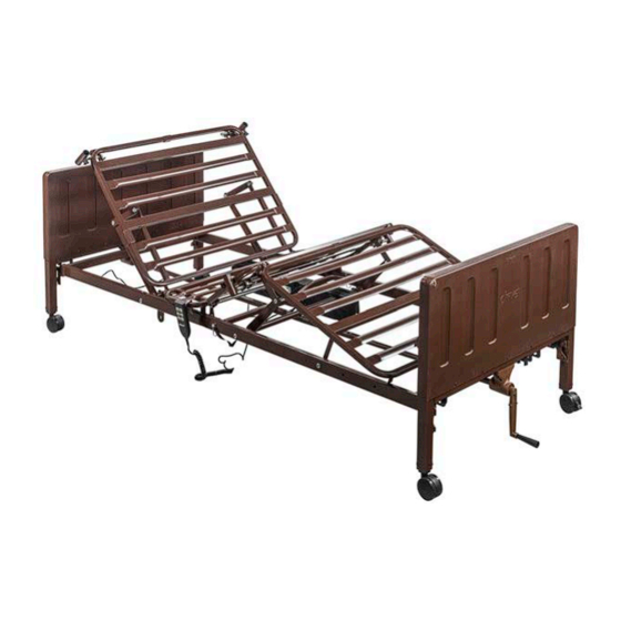
DRIVE DELTA PRO BED SYSTEM
Semi and Full Electric Bed Designs
Model # 15030N / 15033NC / 15235N / 15003PN / 15004PN / 15005LPN
OWNER'S ASSEMBLY AND OPERATING MANUAL
This manual must be given to the Owner/User of this bed and
should be read carefully before putting this product into use.
Keep manual in an accessible location for future reference.
Series manual VER.A.3.21
Semi- Electric Dual motor (15030N)
Full Electric Low Linear Motor (15005LPN)
Additional Configurations Available
Advertisement
Table of Contents

Related Manuals for Drive DELTA PRO 15030N


Summary of Contents for Drive DELTA PRO 15030N
- Page 1 DRIVE DELTA PRO BED SYSTEM Semi and Full Electric Bed Designs Model # 15030N / 15033NC / 15235N / 15003PN / 15004PN / 15005LPN OWNER’S ASSEMBLY AND OPERATING MANUAL Semi- Electric Dual motor (15030N) Full Electric Low Linear Motor (15005LPN)
-
Page 2: Table Of Contents
The user is responsible for reading and understanding the product user manual. Drive DeVilbiss Healthcare is not responsible for any injuries resulting from failure to comply with the instructions and precautions in this manual. -
Page 3: Document Symbols & Warning Labels
STANDARD SYMBOLS USED IN THIS MANUAL This manual includes important information about the safety of personnel and equipment. As you read through this manual be aware of the symbols and their meanings. DANGER Information that appears under the DANGER symbol concerns the protection of personnel from direct and pending hazards that, if not avoided, will result in immediate, serious personal injury or death in addition to damage of the equipment. - Page 4 PRODUCT SYMBOLS Symbols Description Symbols Description Type BF applied part equipment. Recycle the item in accor- IEC 60601-2-52: The applied part includes all dance with local regulations. parts of the medical bed that are within reach of the patient, even if they are underneath the mattress support surface.
- Page 5 WARNING LABELS...
-
Page 6: General Safety
DANGER SHOCK HAZARD Possible injury or Death may occur if accessories are not provided and therefore tested by Drive DeVilbiss Healthcare. Please contact Drive DeVilbiss Healthcare for accessory parts that are compatible with this bed. Possible injury or Death may occur if replacement parts are not provided and therefore tested by Drive DeVilbiss... - Page 7 This bed should not be placed in an oxygen rich environment. CAUTION It is recommended to use Drive DeVilbiss Healthcare compatible lifts with this homecare medical bed. Patient lifts should not be used to transport patients to different locations of the home.
- Page 8 Monitor patient frequently. Use appropriately sized Drive mattresses when using this bed. The mattress must fit firmly against the bed frame and bed side rails. On March 10, 2006 the U S Food and Drug Administration (released guidelines for reducing the risk of hospital bed entrapment entitled, “Hospital bed System Dimensional and Assessment Guidance to Reduce Entrapment”...
- Page 9 Other manufacturer side rails may not be compatible and can lead to entrapment issues or harm to patients/residents. Only Drive DeVilbiss compatible side rails may be used with this bed. Make sure rails are properly secured to frame to decrease the risk of entrapment.
-
Page 10: Intended Use And Contraindications
A mattress may not be included with this bed. It is recommended that a standard 36” wide mattress that is made to fit an 80”or 84” (extension) length bed frame is used, such as a Drive DeVilbiss Healthcare standard inner spring, foam, fiber, or pressure redistribution mattress. -
Page 11: Packaging And Handling
UNPACKING Check cartons for any obvious damage to packaging or contents. If damage is evident, contact your local Drive Medical dealer/provider. Remove any loose packaging from the cartons. -
Page 12: Assembly Instructions
Refer to Fig (color chart) to determine if you have the correct components to assemble the desired bed design. Bed Kit # 15030N – Semi Electric Standard Dual Motor Confirm that all parts are present: A. Headframe Assembly B. Foot frame Assembly C. Drive Shaft D. Fixed Pin(s) E. Headboard Assembly F. Footboard Assembly G. Hand Crank H. - Page 13 Bed Kit # 15235N- Full Electric Low Dual Motor Confirm that all parts are present: A. Headframe Assembly B. Foot frame Assembly C. Drive Shaft D. Fixed Pin(s) E. Low Headboard Assembly F. Low Footboard Assembly G. Hand Crank H. 4 Casters (2 locking, 2 unlocking) I.
- Page 14 Bed Kit # 15004PN- Semi Electric Standard Linear Motor Confirm that all parts are present: A. Headframe Assembly B. Foot frame Assembly C. Drive Shaft D. Fixed Pins x 4 E. Twist knobs x 4 F. Head Actuator Bar G. Foot Actuator Bar H.
- Page 15 Bed Kit # 15005LPN- Full Electric Low Linear Motor Confirm that all parts are present: A. Headframe Assembly B. Foot frame Assembly C. Drive Shaft D. Fixed Pins x 4 E. Twist knobs x 4 F. Head Actuator Bar G. Foot Actuator Bar H.
-
Page 16: Frame Assembly
A) FRAME ASSEMBLY Place both ends of the frame/sleep surface on their side and align the flange with the receptacle as shown. - Page 17 To attach the head and foot sections, interlock the two sides together by sliding the frames toward each other. Secure the frame assembly and lock each end into position by inserting the cotter pin as shown (Figure A). Secure the cotter pin with the attached clasp. Repeat on the opposite side.
- Page 18 Figure B To disassemble the head and foot section, remove cotter pin and clasp and separate sections.
-
Page 19: Motor Installation
B) MOTOR INSTALLATION There are two general methods for the installation of motors to your Delta Pro Bed System. Utilize whichever method is more comfortable for you to assemble. Note- Images below are examples of dual motor installation only. A) INSTALLATION METHOD A - Installing while bed frame is on its side with no bed ends. The motor may be installed on the bedframe when the frame is standing on its side prior to bed ends attachment. -
Page 20: Dual Motor Configurations : Bed Kit #15030N, 15033Nc, And 15235N
Bed Kit # 15030N, 15033NC and 15235N – Dual Motor Configurations* 1. Before installing motor, ensure hand pendant cable is plugged into motor as shown in Fig C. Figure C 2. To prepare motor for installation, remove locking caps on the top of the motor by sliding them off. 3. - Page 21 INSTALLING THE HI/LO MOTOR* Prior to installing ensure that the Drive shaft has been adjusted to the full electric push pin location. 1. Attach the Hi/lo motor with bracket onto the two center holes found on the foot frame assembly and secure with the 2 twist knob screws.
-
Page 22: Linear Motor Configurations: Bed Kit #15004Pn And 15005Lpn
Bed Kit # 15004PN and 15005LPN– Linear Motor Configurations Preparing the motor for installation: Attach the head motor and control box to the bracket on the foot frame by aligning the motor and frame holes. Secure motor with 2 spring twist knobs. See Fig E. Figure E Attach head actuator tube to head actuator bar on headframe assembly. - Page 23 Slide Driveshaft under length of the bed. Lift the Head Section of the bed frame and install the Spring Loaded end of the Drive Shaft to Head Board drive pin, then install foot end of the Drive Shaft into the Foot board drive pin OR Hi/Lo motor coupler if applicable.
-
Page 24: Headboard Assembly
HEADBOARD ASSEMBLY Note- Headboard Assembly should be completed AFTER Method A motor installation OR Headboard Assembly should be completed PRIOR to Method B Motor Installation. Install casters onto Standard (15546) or Low (15547) bed ends by inserting the stem of the caster into the leg receptacle. It is recommended to install one locking caster and one non-locking caster on each bed end. -
Page 25: Bed Operation
BED OPERATION CRUSH HAZARD Crush point exists due to LOW BED CLEARANCE. DO NOT place feet or other limbs under the frame when lowering the bed. When lowering the bed, be aware this may cause INJURY if limbs or personal items interfere with bed movement. Stay clear of the frame and ensure children and/or pets are not under the bed before lowering. -
Page 26: Dual Motor Configurations : Bed Kit #15030N, 15033Nc, And 15235N
Battery function should be checked periodically to insure battery health. The battery should be removed if it no longer has a charge or if leakage from battery occurs. • Drive DeVilbiss Healthcare cannot be held responsible for improper backup use. • When battery is installed, unplugging the bed from mains power will not switch bed off. -
Page 27: Linear Motor Configurations: Bed Kit #15004Pn And 15005Lpn
Bed Kit # 15004PN and 15005LPN– Linear Motor Configurations HAND PENDANT*** These models come with a 4 Function hand held Raise Head Pendant. Lower Head Raise Foot - First row buttons control raising and lowering the Head Lower Foot Section. Raise Head/Foot - Second Row buttons control raising and lowering the Lower Head/Foot... - Page 28 The FDA Guidance document identifies specific dimensional criteria on potentially injury-threatening gaps and spaces that can occur between bed system components, such as side rails when improperly installed. Drive DeVilbiss Healthcare’s 15561/15571 beds and approved accessories are manufactured to be in conformance with these guidelines.
-
Page 29: Bed Rail Installation
BED RAIL ASSEMBLY Full Bed Rails: Your Delta Pro Bed System is compatible with Full Bed Rails (15561FRAIL) that expand to adjust for bed articulation. To install lift the head section and find the rail receptacle located on the frame of the bed as shown (Fig A). Pull receptacle outward and return head section to the flat position. - Page 30 Half Bed Rails: Your Delta Pro Bed System is compatible with Half Bed Rails (15561HRAIL). To install half rails, locate the label located on the head section of the frame (Fig D). The half rail clamp should be installed over this label. Align fixed clamp jaw (Fig E) in front of bed frame rail as shown below.
-
Page 31: Manual Hi/Lo Adjustment Crank & Mattress Retainer
CORRECT INCORRECT When installing bed rail, only place one (1) DO NOT place 2 bed rails on the same rail on bed per side. side of the bed as shown above. WARNING - INCORRECT MOUNTING MAY CAUSE INJURY OR DEATH MATTRESS RETAINER ADJUSTMENT Before a mattress is placed onto the bed deck, flip up the mattress retainer to reduce mattress movement HI/LO ADJUSTMENT CRANK... -
Page 32: Additional Accessories
ADDITIONAL ACCESSORIES Not included but compatible with your Delta Pro bed system and available from Drive DeVilbiss : 1. 15044CSET- Additional set of Caster- Four (4) 3” Casters 2. 15561EXT: 4” Bed Length Extender The Delta Pro bed sleep surface can be extended in length by adding a 4” bed extender, Model #15561EXT. To assemble follow the steps below. - Page 33 3d. Assemble motor to foot end mounting pins. 3e.Place Head and Foot Frame onto Transporter Deck. 15571TRANS & 15561TRANSC Casters included with 15561TRANSC 5. Item# 13009KT-BV: Trapeze The Delta Pro bed can be used with a free standing trapeze or a Drive Medical frame mounted trapeze.
-
Page 34: Maintenance & Warranty
MAINTENANCE & WARRANTY Drive recommends the following maintenance and cleaning procedures be conducted between users. ELECTRONICS • Check all controls to make sure all functions work properly. • Foot control • Head control • Check all cables for damaged or frayed wires. -
Page 35: Parts And Service
Drive DeVilbiss Healthcare tech support. If a Drive DeVilbiss Healthcare technician is required, one will be provided by Drive DeVilbiss Healthcare at our discretion. Most parts can be shipped next day air at the customer’s expense. This warranty is extended to the original purchaser of the equipment. -
Page 36: Additional Warning
Keep all moving parts, including the main frame, mattress After the bed has been assembled, always test to make deck (head and foot sections) and all drive shafts free of sure that all sections of the bed are properly and securely obstruction (i.e. - Page 37 Drive Medical recommends that the mattress be centered on the bed frame. Otherwise, individuals may become The total weight limit of the Drive Medical 36 inch (91.4cm) entangled between the bed rail and the bed frame. wide Manual/Semi-Electric/Full Electric bed is 450 pounds...
-
Page 38: Electromagnetic Emissions & Immunity
ADJUST, including cables specified by the manufacturer. Otherwise, degradation of the performance of this equipment could result.” The use of accessories and cables other than those specified by Drive DeVilbiss Healthcare, with the exception of accessories and cables sold by Drive DeVilbiss Healthcare for use with the SEMI ELECTRIC BED WITH MANUAL LEG ADJUST as replacement parts for internal components, may result in increased EMISSIONS or decreased IMMUNITY of the SEMI ELECTRIC BED WITH MANUAL LEG ADJUST. - Page 39 EMI COMPLIANCE TABLE Table 1 - Emission Phenomenon Compliance Electromagnetic environment RF emissions CISPR 11 Professional healthcare facility environment and homecare environment Group 1, Class B Table 2 - Enclosure Port Phenomenon Basic EMC standard Immunity test levels Professional healthcare facility environment and homecare environment Electrostatic Dis- IEC 61000-4-2...
- Page 40 Table 4 - Input AC power Port Phenomenon Basic EMC standard Immunity test levels Professional healthcare facility environment and homecare environment Electrical fast transients/ IEC 61000-4-4 ±2 kV burst 100kHz repetition frequency Surges IEC 61000-4-5 ±0.5 kV, ±1 kV Line-to-line Conducted disturbances IEC 61000-4-6 3V, 0.15MHz-80MHz...
- Page 41 Allow a slight pause between adjustments and avoid pressing multiple buttons at the same time. If pendant buttons are depressed too rapidly or multiple buttons are pressed at the same time, the desired feature may not activate. Simply release the pendant button, permit a slight pause and then activate the next operation. Always unplug the bed from the electrical outlet before cleaning.
-
Page 42: Troubleshooting
Lower 2. Ensure Hand Crank is properly engaged into bed end gear box. 3. Drive Shaft may not be installed or is incorrectly installed. Ensure Drive Shaft is properly connected to both Bed End gear boxes. 4. To work properly, Bed Ends must be installed as a set: Bed End at Head Section will say “HEAD”... -
Page 43: Appendix: A Guide To Bed Safety Bed Rails
APPENDIX SPECIAL NOTE For your convenience, we have provided the April 2010 edition of the FDA’s guide to bed safety. This information from the FDA’s brochure, published by Hospital Bed Safety Workgroup, is replicated verbatim; the latest version is available at http://www.fda.gov. A Guide to Bed Safety Bed Rails in Hospitals, Nursing Homes and Home Health Care: The Facts Bed Rail Entrapment Statistics Today there are about 2.5 million hospital and nursing home beds in use in the United States. - Page 44 • Strangling, suffocating, bodily injury or death when patients or part of their body are caught between rails or between the bed rails and mattress. • More serious injuries from falls when patients climb over rails. • Skin bruising, cuts, and scrapes. •...
- Page 45 To report an adverse event or medical device problem, please call FDA’s Med Watch Reporting Program at 1-800-FDA-1088. For additional copies of this brochure, see the FDA’s Hospital Bed website. For more information about this brochure, contact Beryl Goldman at 610-335-1280 or by e-mail at bgoldman@kendalout-reach.org.
- Page 46 NOTES:...
- Page 47 NOTES:...
- Page 48 99 Seaview Boulevard Port Washington, NY 11050 Phone: 516-998-4600 Toll Free: 877.224.0946 Fax: 516.998.4601 www.drivemedical.com Delta Pro Manual VER.A.3.21...
Need help?
Do you have a question about the DELTA PRO 15030N and is the answer not in the manual?
Questions and answers