
Related Manuals for Danfoss DEVItector II V2


Summary of Contents for Danfoss DEVItector II V2
- Page 1 User Guide DEVItector™ II V2 Tracing and correcting faults in electric heating cable systems Intelligent solutions with lasting effect Visit devi.com...
-
Page 2: Table Of Contents
Appendix A................... . . 31 2 | ©Danfoss | FEC | 2022.07... -
Page 3: Warnings
The user must be aware that, if the equipment is Danfoss A/S doesn’t take responsibility for burned used in a manner not specified by the manufacturer, property. -
Page 4: About This Guide
The equipment and this guide are intended solely for location of the fault. personnel working in the interest of Danfoss A/S. No part of the equipment is to be resold or handed over This is done by high voltage burning, in which the to other parties. -
Page 5: The Equipment
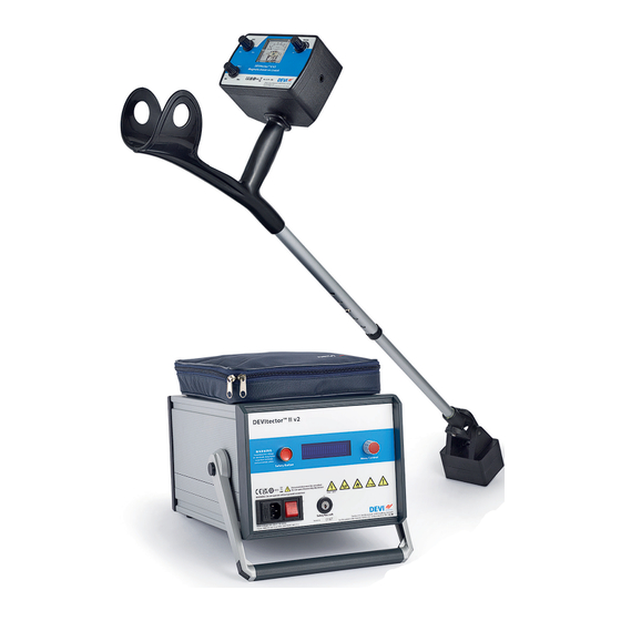
Fig. 3: Photo of High Voltage Unit (left), the Magnetic tracer on crutch (mid) and the Magnetic tracer - Hand held (right). Note: The photos are not to scale. BC421332622232en-010101 2022.07 | FEC | ©Danfoss | 5... -
Page 6: Packing List
HVU. 5. Two yellow high voltage outlet cables attached to the HVU within the top bag. The cables are tied together to minimize radio noise emission. 6. This User Guide. 6 | ©Danfoss | FEC | 2022.07 BC421332622232en-010101... -
Page 7: User Interfaces
Insert key (not shown) and turn right 90° to activate the mains supply. 4. Safety Button: Must be engaged (pressed down) continously during burning operation. Releasing the button will switch OFF the high voltage output. BC421332622232en-010101 2022.07 | FEC | ©Danfoss | 7... -
Page 8: Hvu Safety Markings
The label signifies that the device is heavy and needs special care. 10 kV~ / 400 V⎓ Fig. 7: High Voltage label located on the front display. The label signifies potentially dangerous levels of electrical energy. 8 | ©Danfoss | FEC | 2022.07 BC421332622232en-010101... -
Page 9: User Interface Of Magnetic Tracer On Crutch
Can only be used together with DEVItector™ burner unit while in trace mode. Volume: Controls the acoustic amplification of the sensor signal. Turn clockwise to increase, and counterclockwise to decrease amplification. BC421332622232en-010101 2022.07 | FEC | ©Danfoss | 9... -
Page 10: Menus Of Devitector™ Ii V2
The menu has no user interaction. The item “V1.00” indicates the software version of the HVU. Fig. 16: Main Menu: You can select among three modes: Burn, Trace and Setup. Each of those has their own submenu as shown below. 10 | ©Danfoss | FEC | 2022.07 BC421332622232en-010101... - Page 11 Fig. 18: Trace Menu: The “TRACE RUN” displays the Voltage and current of the signal. Safety Button on/pressed Fig. 19: Setup Menu: Here you select the Autostop current at which the burning operation is halted. BC421332622232en-010101 2022.07 | FEC | ©Danfoss | 11...
- Page 12 The conductivity of the carbon bridge must be several times larger than the heating conductors in order to short circuit the remainder of the heating cable. 12 | ©Danfoss | FEC | 2022.07 BC421332622232en-010101...
- Page 13 2. Press the knob once to enter the setup menu. 3. Select a proper value of the tracing voltage. 3. Turn knob to set the Autostop Current to the desired value, e.g. 1,00 Ampere. BC421332622232en-010101 2022.07 | FEC | ©Danfoss | 13...
-
Page 14: Troubleshooting A Heating System Installation
If it is missing, continue with step 4. 6. If no faults appeared in the above tests, the heating element/heating cable is probably faulty. If a mistake occurs, check the heating element/ cable before proceeding. 14 | ©Danfoss | FEC | 2022.07 BC421332622232en-010101... -
Page 15: Common Types Of Electric Heating Cables
End coupling: Fig. 21: Four types of heating cable. The first two cables are single conductor cables, and the last two are twin conductor cables. Drawings indicates heating conductors as “heating cable”. BC421332622232en-010101 2022.07 | FEC | ©Danfoss | 15... -
Page 16: Fault Symptoms
Will not show No heat RCD-relay cut off Burnt fuse Twin conductor or fuse is burnt out with screen Fault no. 1 Fault no. 4 Fault no. 5 = No action! = Not possible! 16 | ©Danfoss | FEC | 2022.07 BC421332622232en-010101... -
Page 17: Gallery Of Heating Cable Faults
The carbon bridge is then used for tracing. In this case the idea is to burn a connection between the disrupted conductor and the other conductor. BC421332622232en-010101 2022.07 | FEC | ©Danfoss | 17... - Page 18 No burning is required unless the short circuit is unstable. The insulation resistance of the heating cable is OK. 18 | ©Danfoss | FEC | 2022.07 BC421332622232en-010101...
- Page 19 In some cases you may go directly to tracing, and in some cases you will need to burn the necessary connection for use in the tracing process. For appropriate use of the equipment, please proceed to the next section. BC421332622232en-010101 2022.07 | FEC | ©Danfoss | 19...
-
Page 20: Burning And Tracing
OFF. The thermo fuse will automatically restore On condition after approx. 10–20 min. Note: Do not switch power OFF when HVU is cooling down. Fig. 22: Photo of HVU-treated heating cable installed in open air on sand 20 | ©Danfoss | FEC | 2022.07 BC421332622232en-010101... -
Page 21: Burning Procedure
11. Select “HVon” and activate (the circular indicator in the display is highlighted). The role of the HV- pulse is to “shoot” through the insulation thus paving the way for the DC current. BC421332622232en-010101 2022.07 | FEC | ©Danfoss | 21... -
Page 22: Tracing Procedure
The signal should vanish where the fault is, that is when you pass the fault, the tracer readout drops to the low level adjusted on the meter. 22 | ©Danfoss | FEC | 2022.07 BC421332622232en-010101... -
Page 23: Guidelines For Tracing An Area
Using the high voltage signal may destroy the it quickly. If it does not, then proceed to Step 2. carbon bridge temporarily. BC421332622232en-010101 2022.07 | FEC | ©Danfoss | 23... - Page 24 Fig. 23 Step 1: Sketch showing a room having two heating elements of which only one is faulty. Fig. 24 Step 2: Trace the floor along parallel lanes a distance D=50 cm apart, shown as transparent yellow. 24 | ©Danfoss | FEC | 2022.07 BC421332622232en-010101...
- Page 25 Fig. 25: Step 3: Trace the area around the marks of step 2. (shown as yellow areas around marks X). Fig. 26: An alternative tracing direction along lanes marked will result in the same search area marked . BC421332622232en-010101 2022.07 | FEC | ©Danfoss | 25...
-
Page 26: Hard Cases Of Tracing
Remove the burnt section of the cable so only undamaged cable remains. Find a proper length of heating cable which is of similar type and linear resistance [Ω/m] as the installed cable. 26 | ©Danfoss | FEC | 2022.07 BC421332622232en-010101... -
Page 27: Glossary
Conductor Common term for either a heating wire or the screen 10. Ordering information For safety reasons do only use replacements delivered from Danfoss A/S according to the table below. Item no. Description EAN no. -
Page 28: Data Sheet
For burner and tracer: indoor and outdoor use. Temperature range: 5 ºC to 40 ºC. Altitude: up to 2000 m above sea level. Humidity at 31 ºC: max. 80% linear falling to 50% at 40 ºC. 28 | ©Danfoss | FEC | 2022.07 BC421332622232en-010101... - Page 29 The equipment has been tested by Intertek according to EN/IEC 61010-1 with amendments, EN/IEC 61010-2-030 with amendments and EN/IEC 61326-1 with amendments. Environment For HVU tracer mode: indoor and outdoor use. Temperature range: 5 ºC to 40 ºC. BC421332622232en-010101 2022.07 | FEC | ©Danfoss | 29...
-
Page 30: Warranty
The repair or replacement. electricians. All work will be invoiced in full if Danfoss is required to inspect or repair faults that have arisen as a The decision to either repair or replace will be solely at the result of any of the above. - Page 31 If the above mentioned safety regulations will not be respected and maintained, the manufacturer, Danfoss A/S, will be entitled to withdraw the DEVItector™ units from the holder.
- Page 32 User Guide DEVItector™ II V2 Danfoss A/S Nordborgvej 81 6430 Nordborg, Syddanmark Denmark 08091600 & BC421332622232en-010101 © Danfoss | FEC | 2022.07 | 32...
Need help?
Do you have a question about the DEVItector II V2 and is the answer not in the manual?
Questions and answers