Advertisement
Quick Links
This document contains installation instructions for the switches of the following versions:
200M-RS.E4
200M-RS.E5
200M-RS.E6
200M-2.0.1.E
200M-2.1.4.E
200M-2.1.7.E
The notes stated in italics relate only to use in alarm systems complying with
CSN EN 50131-1 ed.2.
The package contains
1
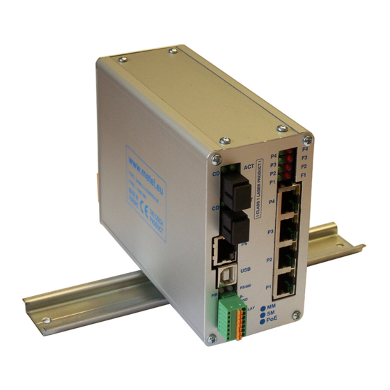
1.1 Switch
1.2 Power Supply Connector (modification BOX only)
1.3 DIN Rail-mountable kit (modification BOX only)
1.4 Mounting kit for a wall placement (modification BOX only)
1.1 Mounting kit for a pole placement (optional accessories for IP65 modification)
1.2 Installation Manual
1.3 Product Datasheet
Optional Accessories
2
Mounting kit for placement on column.
Ordering name:
Software
3
The following freeware applications are available for download from
Software management
Software for RS485 communication over virtual COM ports
USB drivers
All applications are compatible with OS Windows XP, Vista and Windows 7.
www.metel.eu
Installation Manual
rev. 20120510
SW-HOLDER
2G-RS.E4
2G-RS.E5
2G-RS.E6
2G-2.0.1.E
2G-2.1.4.E
2G-2.3.0.E
2G-0.1.4.E
2G-0.1.8.E
2G-2.1.7.E
1/14
www.metel.eu
SIMULand
VcomNet
USB-driver
Advertisement

Related Manuals for Metel 200M-RS.E4


Summary of Contents for Metel 200M-RS.E4
- Page 1 Installation Manual rev. 20120510 This document contains installation instructions for the switches of the following versions: 200M-RS.E4 2G-RS.E4 200M-RS.E5 2G-RS.E5 200M-RS.E6 2G-RS.E6 200M-2.0.1.E 2G-2.0.1.E 200M-2.1.4.E 2G-2.1.4.E 200M-2.1.7.E 2G-2.3.0.E 2G-0.1.4.E 2G-0.1.8.E 2G-2.1.7.E The notes stated in italics relate only to use in alarm systems complying with CSN EN 50131-1 ed.2.
-
Page 2: Mounting And Installation
Mounting and Installation 4.1 BOX Modification The package contains two screws M3x6 for flat surface placement and DIN holder with bolts M3x6 for upright or parallel mounting to DIN35 rail. When using in alarm systems acc. to CSN EN 50131-1 ed.2 it is necessary to place... - Page 3 4.2 RACK Modification 4.2.1 Turn off the rack before installation, carefully place the switch on the two side rails in a free slot position at the rack and push the switch until it is properly inserted. 4.2.2 Visually check the power connector on the switch that it is properly attached to the rack power connector.
-
Page 4: Power Connection
Power Connection 5.1 BOX Modification 5.1.1 For non-PoE application it is recommended to use one of the the following power supplies. Supply Maximum Operational Power Temperature SU-230/4870H -40°C...+50°C SUP-48.120 120W -25°C...+70°C TRF-2420T -40°C...+50°C TRF-2420T-IP55 -40°C...+50°C TRF-2420T-IP55H -40°C...+50°C QS10.481 240W -25°C...+70°C... - Page 5 Supply Maximum Operational Power Temperature SU-230/4870H -40°C...+50°C SUP-48.120 120W -25°C...+70°C QS10.481 240W -25°C...+70°C 5.1.6 Power connection is described in the figures below. 5.1.7 If redundant power is required use redundant power input (see the right figure). REDUNDANT SUPPLY GND(PE)
- Page 6 5.3.2 PoE Application 5.3.2.1 Power connection is described in the figures below. 5.3.2.2 Use 1 - 1.5 mm² wire between the power supply and the switch. It is recommended to tin the wire or to use a compression joint.
- Page 7 Overvoltage Protection Grounding 6.1 BOX Modification 6.1.1 Ground the switch acc. to the right figure. 6.1.2 Ground resistance must not exceed 10 Ω. 6.1.3 Use min. 4mm wire. 6.1.4 With higher ground resistance efficiency of overvoltage protections decreases. 6.1.5 Grounding cable length should be kept as short as possible.
- Page 8 7 Fiber Optic Port Connection 7.1 The switches are equipped with fiber ports with laser class 1 and wavelength 1310nm and 1550nm. WARNING! Do not stare into the beam. Laser is invisible and is hazardous to your eyes! We recommend using protection glasses with laser beam absorption.
- Page 9 Topology Topology Point-to-point and Bus 8.1.1 Switches support connection both in topology point-to-point and optical bus. The switches are already fully operational in default setting and priority SLAVE. Topology Optical Ring 8.2.1 Switches support topology optical ring. Before the ring is closed it is necessary to set Ring ID for all switches and one switch must be in MASTER mode.
-
Page 10: Switch Configuration
Switch Configuration 9.1 IP Address, Mask and Gateway 9.1.1 Every switch has pre-set default configuration with mask 255.255.255.0 and following IP addresses: 200M-RS.E4 10.19.0.x 2G-RS.E4 10.16.0.x 200M-RS.E5 10.20.0.x 2G-RS.E5 10.17.0.x 200M-RS.E6 10.21.0.x 2G-RS.E6 10.18.0.x 200M-2.0.1.E 10.22.0.x 2G-2.0.1.E 10.23.0.x 200M-2.1.4.E 10.9.0.x 2G-2.1.4.E... - Page 11 9.1.6 Select a device using the left mouse button and using the right mouse button you can select „Configuration/Online configuration“. 9.1.7 Enter password. Default is “metel”. 9.1.8 In tab „IP“ insert required IP address, mask and gateway. Confirm settings by pressing button „OK“ or „Apply“.
- Page 12 9.2.4 Launch SIMULand – for download from www.metel.eu 9.2.5 In menu select „Tools/USB Device“. 9.2.6 Select the port assigned by the system and press the „Configuration“ button. 9.2.7 Enter password. Default is “metel”. 9.2.8 Continue with steps defined in Remote management (9.1.8) 12/14...
- Page 13 9.3 Configuration Required for Properly Working Ring - Before the Optical Ring is Closed! 9.3.1 For proper functioning of ring set in menu “Ring” - it is required to have “Enabled” ring functionality on all switches on ring - it is required to have one switch in “Master” mode - all switches in the ring must have the same ring number “Ring ID”...
- Page 14 9.4 Indication of Optical Ring Failure or Sabotage 9.4.1 In case of ring interruption (failure or sabotage) the communication is redirected in 30ms. The change of ring state (from 'loop' to 'backup') can be mapped to a relay output on every switch. For 200M(2G)-RS.E6 devices this behavior is pre- set.
Need help?
Do you have a question about the 200M-RS.E4 and is the answer not in the manual?
Questions and answers