Advertisement
Quick Links
This document contains installation instructions for the switches of the following versions:
200M-2.0.4.ECA
200M-2.0.4.ECB
200M-2.0.4.H-ECA
200M-2.0.4.H-ECB
1 The package contains
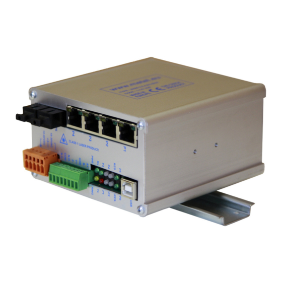
1.1 Switch
1.2 Power Supply Connector (modification BOX only)
1.3 DIN Rail-mountable kit (modification BOX only)
1.4 Mounting kit for a wall placement (modification BOX only)
1.5 Installation Manual
1.6 Product Datasheet
2 Software
The following freeware applications are available for download from
Management software
Software for RS485 communication over virtual COM ports
USB drivers
All applications are compatible with OS Windows XP, Vista and Windows 7 (32, 64 bit).
3 Mounting and Installation
3.1 BOX Modification
The package contains two screws M3x6 for flat surface placement
and DIN holder with bolts M3x6 for upright or parallel mounting to DIN35 rail.
www.metel.eu
Installation Manual
rev. 20110418
2G-2.0.4.ECA
2G-2.0.4.ECB
2G-2.0.4.H-ECA
2G-2.0.4.H-ECB
2G-2.0.4.S-ECA
2G-2.0.4.S-ECA
1/11
www.metel.eu
SIMULand
VcomNet
USB-driver
Advertisement

Related Manuals for Metel 200M-2.0.4.ECA


Summary of Contents for Metel 200M-2.0.4.ECA
- Page 1 Installation Manual rev. 20110418 This document contains installation instructions for the switches of the following versions: 200M-2.0.4.ECA 2G-2.0.4.ECA 200M-2.0.4.ECB 2G-2.0.4.ECB 200M-2.0.4.H-ECA 2G-2.0.4.H-ECA 200M-2.0.4.H-ECB 2G-2.0.4.H-ECB 2G-2.0.4.S-ECA 2G-2.0.4.S-ECA 1 The package contains 1.1 Switch 1.2 Power Supply Connector (modification BOX only) 1.3 DIN Rail-mountable kit (modification BOX only)
- Page 2 2/11...
-
Page 3: Power Connection
4 Power Connection 4.1 BOX Modification 4.1.1 For non-PoE application it is recommended to use one of the the following power supplies. Supply Maximum Operational Power Temperature SU-230/4870H -40°C...+50°C SUP-48.120 120W -25°C...+70°C TRF-2410T -40°C...+50°C TRF-2410T-IP55 -40°C...+50°C TRF-2410T-IP55H -40°C...+50°C QS10.481 240W -25°C...+70°C... - Page 4 4.1.8 For use in alarm systems connect the switch to a supply complying with CSN EN 50131-1 ed.2. Connect the supply according to the figure below. 5 Overvoltage Protection Grounding 5.1 BOX Modification 5.1.1 Ground the switch. 5.1.2 Ground resistance must not exceed 10 Ω.
- Page 5 Fiber Optic Port Connection 6.1 The switches are equipped with fiber ports with laser class 1 and wavelength 1310nm and 1550nm. WARNING! Do not stare into the beam. Laser is invisible and is hazardous to your eyes! We recommend using protection glasses with laser beam absorption.
- Page 6 7.3 Topology Optical Ring Complying with CSN EN 50131-1 ed.2. Default switch setting 200 and 2G-RS.E Other switches Ring enabled Ring ID Relay Set to ring interruption detection (RING-OK) RS485 port setting 9600kbps 9600kbps 8-N-1 8-N-1 Setting of Tx and Rx address Rx: 239.192.168.1...
-
Page 7: Switch Configuration
200M-RS.E6 10.21.0.x 2G-RS.E6 10.18.0.x 200M-2.0.1.E 10.22.0.x 2G-2.0.1.E 10.23.0.x 200M-2.1.4.E 10.9.0.x 2G-2.1.4.E 10.10.0.x 200M-2.0.4.ECA 10.24.0.x 2G-2.3.0.E 10.15.0.x 200M-2.0.4.ECB 10.25.0.x 2G-0.1.4.E 10.13.0.x 2G-0.1.8.E 10.14.0.x x – corresponds to the last number of MAC address. Please change the IP address if required. See the figure below. - Page 8 8.1.6 Select a device using the left mouse button and using the right mouse button you can select „Configuration/Online configuration“. 8.1.7 Enter password. Default is “metel”. 8.1.8 In tab „IP“ insert required IP address, mask and gateway. Confirm settings by pressing button „OK“ or „Apply“.
- Page 9 8.2.4 Launch SIMULand – for download from www.metel.eu 8.2.5 In menu select „Tools/USB Device“. 8.2.6 Select the port assigned by the system and press the „Configuration“ button. 8.2.7 Enter password. Default is “metel”. 8.2.8 Continue with steps defined in Remote management (8.1.8) 9/11...
- Page 10 8.3 Configuration required for properly working ring - Before the optical ring is closed! 8.3.1 For proper functioning of ring set in menu “Ring” - it is required to have “Enabled” ring functionality on all switches on ring - it is required to have one switch in “Master” mode - all switches in the ring must have the same ring number “Ring ID”...
- Page 11 8.4 Indication of Optical Ring Failure or Sabotage 8.4.1 In case of ring interruption (failure or sabotage) the communication is redirected in 30ms. The change of ring state (from 'loop' to 'backup') can be mapped to a relay output on every switch.
Need help?
Do you have a question about the 200M-2.0.4.ECA and is the answer not in the manual?
Questions and answers