Table of Contents
Advertisement
Quick Links
Advertisement
Table of Contents

Related Manuals for KAKA Industrial BS-75G


Summary of Contents for KAKA Industrial BS-75G
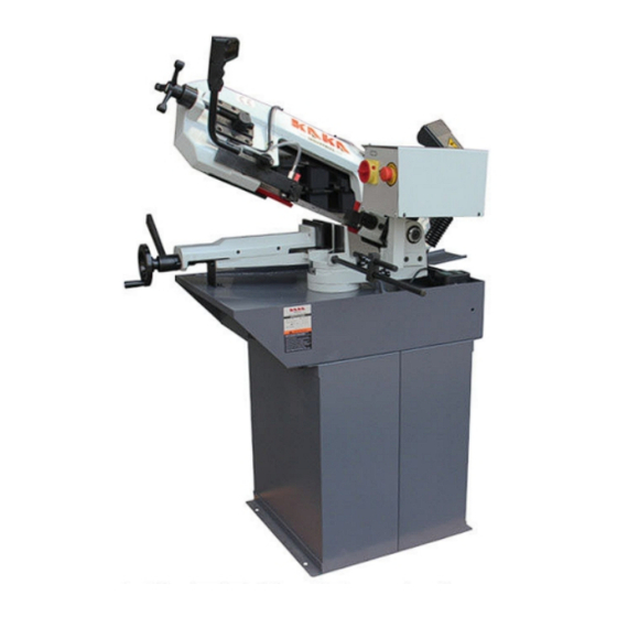
- Page 1 METAL CUTTING BAND SAW MODEL BS-75G Assembly & Operating Instruction...
- Page 2 1. INTRODUCTION This operation instruction manual conforms to the requirements of the 98/37/EEC Machine Directives and subsequent amendments. In the light of this, special attention has been given to safety aspects and accident prevention in the work-place for each stage in the machine’s “life”. Information which could be of particular assistance to the operator has been highlighted.
-
Page 3: Description Of The Machine
Chap. 4 Description of the machine Safety standards complied with during the design and construction of the machine Description of the machine and its components Chap. 5 Main technical data Chap. 6 Handling and transportation Chap. 7 Installation Chap. 8 Start up and operation Devices and their location Tools supplied... - Page 4 EN 292-2 1991 Safety of machinery. Basic concepts and general principles for design. Specifications and technical principles. EN418 1994 Safety of machinery. Emergency stop devices,functional aspects-design principles. - EN 983 1996 Safety requirements related to systems and components for hydraulic and pneumatic transmissions.
-
Page 5: Main Technical Data
risk. Cutting is not permitted, if the bar has not been first locked in the vice. 5. MAIN TECHNICAL DATA Under no circumstances should the following data be altered, this is in order to protect the correct functioning of the machine and to avoid creating safety risks for the operator. MOTOR Three-phase or single-phase Motor Power... -
Page 6: Electrical Connection To The Mains
Encl.2. 7.3 BAND ASSEMBLY Remove the bow guard 47 by unscrewing the screws 125 and the hand wheels 50 (DRAW.7 ENCL.6). Fit the band by inserting it first between the bearings of the blade guide heads and then on the two pulleys, tighten the blade slightly by means of the hand wheel 43 (DRAW.5 ENCL.5) and replace the bow guard. -
Page 7: Cutting Operation
Remember at the end of the operation to loosen the hand wheel to avoid the slackening of the band. B Check that the hand indicates the required cutting angle (vice scale). C Make sure that the bow and the vice are locked by means of the lever 74 (DRAW.3 ENCL.4) D With the motor off, lower the bow and check that at the end of stroke, the band does not touch the counter-vice 4. -
Page 8: Maintenance And Repairs
A. Wear appropriate clothing. The operator’s clothing should not be loose or dangling nor should it have parts which could easily get caught. Sleeves should contain elastic. Belts, rings or chains should not be worn. Long hair should be kept in a net. B. -
Page 9: Description Of Routine Maintenance
If necessary Check functioning of bench lever 9.3 DESCRIPTION OF ROUTINE MAINTENANCE A. Adjustment of the blade guide bearings Loosen the screws 110, rotate the cams 28, so that the blade guide bushings vertically position the blade in axis (DRAW.6 ENCL.5). Tighten the dowels 113 slightly until the blade secured. Loosen the dowels113 slightly (about 1/10 of a turn). - Page 10 11. LIST OF SPARE PARTS DESCRIPTION CODE Q. POS DESCRIPTION CODE Base 001/31 Tank 002/31 Bench lever hub 034/31 Rotating arm 003/31 Locking pin 014/31 Counter-vice 004/31 Antigrease ring 2036/31 1 Vice 005/31 Ring NILOS 32006 044/31 006/31 Blade tightener pin 038/31 Vice lever 007/31...
- Page 11 DESCRIPTION CODE DESCRIPTION CODE Idle pulley spacer bearing 065/31 Screw TPSCEI M10x20 DIN 272/95 7991 Handle 046/05 Eye tie rod M10x50 043/31 Elastic pin 8x36 DIN 1481 330/95 Blade 2060x20x0.9 Z6/10 065/75 Belleville washer 40x20,4x1.5, 458/95 DIN 2093 Screw TE M8x35 DIN 933 216/95 Blade tightener bush 041/38...
- Page 12 DESCRIPTION CODE DESCRIPTION CODE 066/90 1 Remote contr. Switch 032/90 1 CGE MC0A310AT1 Panel 069/90 1 Thermal relay 053/90 1 MT03 Omega raceway 046/90 1 Fitting for cables PG9 213/90 1 Changeover switch 012/90 1 Socket head screw VEMERCSO121177IPA M4x8 Screw TCCC M4x14 DIN 295/95 4 Screw TCCC M4x14...
- Page 13 4. Cover the machine with a sheet, preferably not plastic as it can cause rust due to the humidity condensation. 5. Store the machine in a closed, dust-free place. 12.2 DISMANTLING If the machine must be definitively dismantled, its components must be sub-divided for the purpose of a possible recycle of the materials and for the environment safety.
- Page 14 BAND SAW...
Need help?
Do you have a question about the BS-75G and is the answer not in the manual?
Questions and answers