Table of Contents
Advertisement
Quick Links
Advertisement
Table of Contents

Related Manuals for KAKA Industrial CS-12


Summary of Contents for KAKA Industrial CS-12
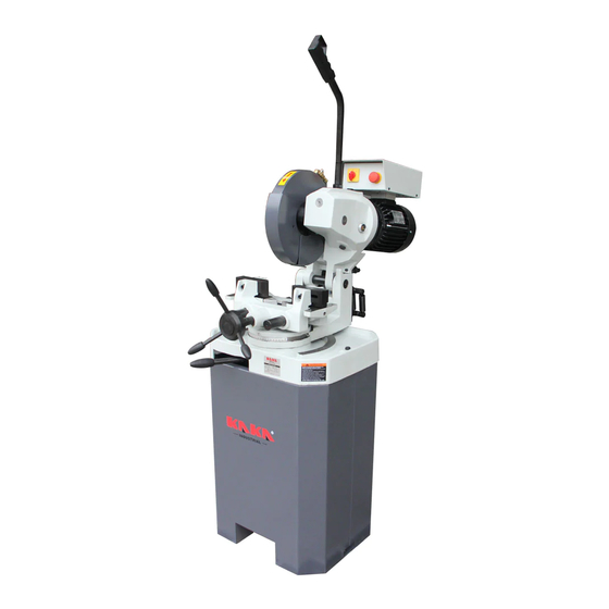
- Page 1 COLD SAW Model: CS-12/CS-14 Opertation Manual...
-
Page 2: Safety Regulations
1.Introduction 1.1 General By means of this operator’s manual you can get acquainted with your circular sawing machine from the range CS-315 and CS-350. We advise you to read the enclosed operator’s manual carefully, so that you will soon be familiar with the operation and maintenance of the machine. - Page 3 CS-315 and CS-350 LOW SPEED SAWING SPEED POS.1:18.5M/MIN IN POS.2: 37M/MIN. CS-315 and CS-350 HIGH SPEED SAWING SPEED POS.1:37M/MIN IN POS.2: 74M/MIN. 2.2 Survey and sketch of dimensions (see fig. 2,01) Dimensions and weight of the machine CS-12 Height(H): 175mm Width(B): 555 mm Depth: 970 mm...
-
Page 4: Description Of Machine
2.3 Requirement of operating site This machine is designed for operating on the site: - Voltage The steady-state AC power supply is 0.9~1.1 times of the rated value. - Frequency 0.99~1.01 times of rated frequency (continuous working) 0.98~1.02 times of rated frequency(short period working) - Harmonics The sum of 2nd-5th distorted harmonic must not exceed 10% of RMS of voltage, maximum 2% of RMS of line voltage is allowed to add to the sum of 6th-30th harmonic. -
Page 5: Intended Use
different adapter can be supplied. 3.2 Intended use According to the choice of saw blade referred in No.5 chapter, it can cut many kind and shape steel. For example CARTON STEEL, ALLOY STEEL, COPPER , ALUMINIUM and so on. But it can not cut flammability and explode material, like natrium and magnesium . -
Page 6: Installation Mounting
4.1 Installation mounting Unpack the machine. • Determine where the sawing machine will be placed, in doing so take into account the feed and discharge of materials, optional built-on accessories, maintenance and repairs. • Remove the plastic plug from the saw head (fig. 4.01 B). If so required a lifting hook M20 DIN 580 can be screwed into the hole. -
Page 7: Operation
from your dealer. The coolant must be diluted in wear in a ratio between 1:10 and 1:20, depending on the kind of material. Add the oil slowly to the water while stirring it continually. The filler cap is positioned at the rear of the machine base. - Page 8 special heat treatment which guarantees high wear resistance. Owing to the micros porous structure the cutting oil is transferred quicker into the saw cut. This means longer life before resharpening and less chance of cold welding. The quality of the saw blade is of great importance. The selection of the correct pitch depends on the material to be sawn.
-
Page 9: Sawing Capacity
Clearance angle (5 and rake angle 7 of the tooth have been selected correctly in view of the material to be sawn, the principle is as foifows. Material Clearance angle Rake angle steel 22" stainless steel Non-ferrous 25" Form of tooth cavity large enough compared to the pitch. A quick removal of the cut material and a correct depth and rounding of the tooth cavity are of the utmost importance. -
Page 10: Installing And Replacing The Saw Blade
Fig.5.03 5.4 Installing and replacing the saw blade • Set the main switch in the off position. • Put the saw head in the upper position. • Open the guards (fig- 5.03A). • Release the socket head screw M8 of the saw spindle (fig. -
Page 11: Clamping The Material
5.7 Clamping the material It is of the utmost importance that the material is safely clamped in the double material vice, so that it cannot tilt over or even move during sawing. In order to work efficiently, the material must always be clamped in such a way that the contact surface of the saw and the material is as small as possible. -
Page 12: Maintenance
• Adjust the material vice to the material • Switch on the machine with the main switch. Select the required speed. • Open the coolant cock on the safety guard (not in case of atomized lubrication). • Start machine with the switch on the pulling rod 6 Maintenance 6.1 General Clean the machine after it has been used and provide rust protection by applying a protective oil. -
Page 13: Troubleshooting
6.3 Grinding the sawblades It is only possible to work efficiently with circular sawing machine when the saw blade is reground in time. When the saw has lost its cutting ability, do not try to continue sawing by puting the handle harder, for this can cause teeth to break and the cost of regrinding doubled, Regrinding should only be done on special machines, constructed for this kind of work. -
Page 14: Parts Lists
PARTS LISTS Part No. Description Qty. Part No. Description Qty. Pedestal Sticker electro cover Sticker general support pump Pump set 230/40QV50HZ screw 6 x 12 Filter Spring washer 6 Screw M6x12 Screw M10 x 100 Screw M6 x 12 Spring washer 8... - Page 15 Part No. Description Qty. Angel Scale Type Shield Spring Rivet 10 Screw M10x100 Nut M10X25 Filter Spring fixed plate Spring fixed plate Washer Base plate Swivel block Greasing nipple Shaft...
- Page 17 Part No. Description Qty. Part No. Description Qty. Nut M10 Vice plate left Ring Vice plate right Mat board Vice jaw at the front Bolt Socket screw Rubber cover Handle rod+knob Pipe hoop Knob Plastic cover knob Boss Knob Guiding shaft Mitre handle complete Vice base Stud...
- Page 19 Part No Description Qty. Part No. Description Qty. Ring Locking ring Push down seat Bearing Bolt Ring Bearing Oil mark Worm shaft Needle bearing Gear housing 350 Circlip Worm wheel Stopper stifled Bush Bearing Circlip Sunken key O-ring Ring Socket screw Dowel pin Bearing block Drain catcher...
- Page 21 Part No Description Qty. Part No. Description Qty. Safety guard Coupling rod Hinged guard Bracket Hinged guard Ring Ring Socket head screw Coupling rod Lever Ring Star knob Tap (cock) Adjusting rod Spindle Coupling rod Bush Connecting pipe Circlip...
- Page 22 Part No Description Qty. Part No. Description Qty. Tie bar complete Switch handle Pinion Lock nut Sunken key Motor Screw Bolt Ring Stop ring...
- Page 23 Part No Description Switch box Cover Sealing tape Screw M4x10 Screw M5x12 Spring washer Motor switch contactor (Dahlander switch) Earth bolt Sticker...
- Page 25 Note: This manual is only for your reference. Owing to the continuous improvement of the machine, changes may be made at any time without obligation on notice.
Need help?
Do you have a question about the CS-12 and is the answer not in the manual?
Questions and answers