Table of Contents
Advertisement
Quick Links
Advertisement
Table of Contents

Related Manuals for KAKA Industrial BS-106G


Summary of Contents for KAKA Industrial BS-106G
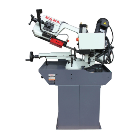
- Page 1 METAL CUTTING BAND SAW MODEL BS-106G Assembly & Operating manual...
-
Page 2: Table Of Contents
Table of contents Introduction……………………………………………………………………………………2 1. Accident prevention and safety instruction……………………………………………..3 1.1 Advice for the operator…………………………………………………………………..3 1.2 The electric equipments according to European Standard “2006/42/EC” which some integrating modifications……………………………………………………………..3 1.3 Emergencies according to European Standard “2006/42/EC”……………..…4 2. Description of machine…………………………………………………………………...4 2.1 Description of machine and its components………………………………………….4 2.2 Intended and unsuitable uses of the machine………………………………………...4 3. -
Page 3: Introduction
INTRODUCTION This operation instruction manual conforms to the requirements of European Standard 2006/42/EC Machine Directives and subsequent amendments. In the light of this,special attention has been given to safety aspects and accident prevention in the work-place for each stage in the machine’s “life”. Information which could be of particular assistance to the operator has been high lighted. -
Page 4: Accident Prevention And Safety Instruction
1. ACCIDENT PREVENTION AND SAFETY INSTRUCTION This machine has been designed to comply with national and community accident-prevention regulations, improper use and / or tampering with the safety devices will relieve the manufacturer of all responsibility. 1.1 Advice for the operator A. -
Page 5: Emergencies According To European Standard "2006/42/Ec
1.3 Emergencies according to European Standard “2006/42/EC”. In the event of incorrect operation of danger conditions, the machine may be stopped immediately by pressing the red emergency button. The casual or voluntary removal of the blade cover of the flywheels causes the stepping-in of a interlock switch that automatically stops all machine functions. -
Page 6: Handling And Transportation
Motor Three-phase or single-phase Motor Power 0.75/1.1 kw Motor revolutions (two speeds) 700 / 1400 rpm Electric pump 0.045 kw Circular @90° 220mm Rectangular @90° 250 x 155 mm Circular @60° 100 mm Capacity Rectangular @60° 80 x 95 mm Circular @45°... -
Page 7: Electrical Connection To The Mains
bow guard. Check that the saw blade is fitted with the correct direction of teeth. Make sure that the saw blade type (dimensions 2450×27×0.9 mm) and its teeth pith are suited to the material to be cut. 5.4 Electrical connection to the mains Install a differential thermo magnetic switch with characteristics suited to the mains. -
Page 8: Special Safety Checks
correction, move it back to the lock position. B. Clamp the material to be cut with #82 hand wheel after having positioned the clamp near the piece to be cut. Lower #86 vice lever. Change selector switch in M position. Turn the main switch to “1” position or “2” position you like, take hold of #7 handle located at the end of head lever and press the button. -
Page 9: Maintenance And Repairs
F. Do not insert foreign bodies into the motor cover and not supply the machine with voltage by tampering with the safety micro switches or main switch. G. Take the necessary precautions to avoid the machine being started by other people during loading, adjustment, piece changing or cleaning. -
Page 10: Information Regarding Environmental Noise
8. INFORMATION REGARDING ENVIRONMENTAL NOISE An environmental noise test carried out on the band saw machine, identical to the machine to which these operation instructions refer, has given the following results: ACOUSTIC RADIATION PRESSURE 1. L =83,2 dB (A) 2. L =90.6 dB (the maximum acceptable value is 140dB). -
Page 11: Parts List
9. PART LIST Item Description Item Description Vice handwheel Washer Bush Drive flywheel Spring 40x20.5x2 Blade Lead screw AXK2035 Pin 10X20 Pin 8X35 Coolar 40 Tension shaft Bearing 608-2Z Microswitch Coolar 25 Knob rod Motor and gear box Slide Washer 10 Bolt M10X25 Bolt M8X16 Pipe fitting seat... - Page 12 PART LIST Item Description Item Description Bolt M8X10 Nut M8 Stop block Rotating arm Bolt M6X8 Bolt M10X30 Fix seat for rotor Column pin 8X30 Bolt M8X25 Eyebolt M12X50 Hand wheel Φ150XΦ18 Spring Tighten bolt M6X10 Leptospira End housing Control box Lead screw AXK3047 Control box support bracket Vice lever...
-
Page 13: Parts Drawing
10. DRAWING... - Page 14 89(2) 94(2) 95(3) 96(3) 111(4) 100(4) 101(4) 110(5) 114(2) 102(2) 118(4) 105(2) 119(2) 125(2) 127(2) 131(4) 132(4) 146(4) 144(4) 143(4) 147(2) 148(2) 152(4) 153(4)
-
Page 15: Electric Drawing
11. ELECTRIC DRAWING... - Page 16 Note: This manual is only for your reference. Owning to the continuous improvement, changes may be made at any time with no obligation on the part of machine. And please note the local voltage for operating machine...