Table of Contents
Advertisement
Quick Links
Advertisement
Table of Contents

Related Manuals for KAKA Industrial BS-126G


Summary of Contents for KAKA Industrial BS-126G
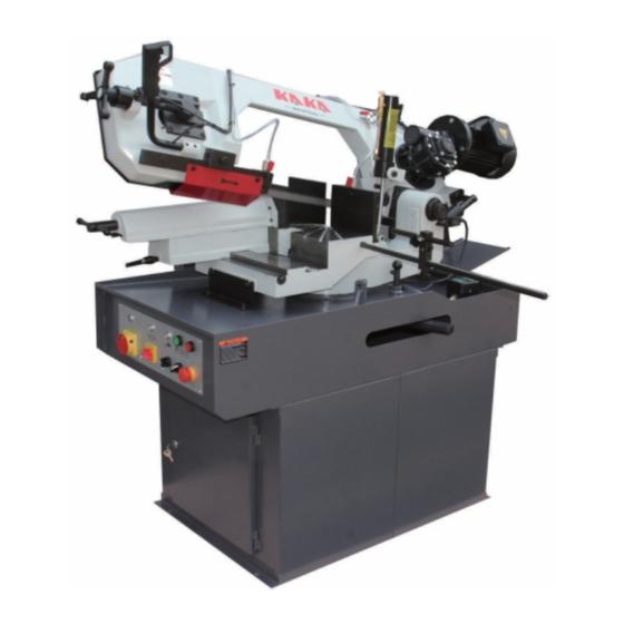
- Page 1 METAL CUTTING BAND SAW MODEL BS-126G Assembly & Operating Instruction...
- Page 2 SAFETY 1. Know your bandsaw. Read the operator’s Manual carefully. Learn the operations, applications and limitation as well as the specific potential hazards peculiar to this band saw. 2. This unit is equipped with a three-prong (grounded) plug for your protection against shock hazards and should be plugged directly into a property grounded three-prong receptacle.
- Page 3 1. INTRODUCTION This operation instruction manual conforms to the requirements of the 98/37/EEC Machine Directives and subsequent amendments. In the light of this , special attention has been given to safety aspects and accident prevention in the work-place for each stage in the machine’s “life”. Information which could be of particular assistance to the operator has been highlighted.
- Page 4 instructions which are an integral part of the machine. Nor is maintenance covered if the instructions supplied are not observed. ● The guarantee will not cover machines which have undergone unauthorized modifications. ● Modification or tampering with the safety devices is strictly forbidden. 3.
-
Page 5: Description Of The Machine
3.2 INDEX OF DRAWINGS,DIAGRAMS AND TABLES ENCL.TYPE DESCRIPTION ENCL NO. CHAP Table Cutting capacity-Selection blade-cutting speeds-Installation plan Drawings Handling and transportation Drawings Blade guides-Blade guide bearings Drawings Vice block-Rotation block Drawings Motor- Tensioning Diagram Electric system Drawings Box exploded view-Machine exploded view Diagram Wiring diagram-Hydraulic diagram... - Page 6 EN 1088 1995 Safety of machinery- Interlocking devices with and without guard- locking. General principles and provisions for design. EN 60204-1 1998 Safety of machinery. Electrical equipment of machines. Part 1: General requirements Sa. EN 60204-2 1990 Electrical equipment of industrial machines. Part 2: Item designation and examples of Drawings, diagrams, tables and instructions.
-
Page 7: Main Technical Data
4.3 Intended and unsuitable uses of the machine The band sawing machine has been designed and built to cut bars, structural steel and ferrous metal pipes in accordance with the instructions contained in this manual. Therefore, the cutting of other materials is not permitted: if the above recommendations are not observed ,... -
Page 8: Machine Start Up And Operation
transportation and handling. If the machine appears to have been damaged, contact us immediately. Fit all the supplied accessories onto the machine such as the bar stop and the roller arm. 7.2 FASTENING OF THE MACHINE The machine will be able to operate in keeping with the technical parameters supplied by us, if it is positioned correctly and fastened securely to the bench or the factory floor so that vibrations are minimal during operation. - Page 9 Code START-STOP MICROSWITCH: situated inside the handle located at the end of the control lever and has safety release action. Code ELECTRIC PUMP Code CUTTING ANGLE DEVICE: to check that cutting inclination is as required Code LOCKING VICE Code BAR STOP Code CONTROL LEVER WITH HANDLE 8.2 TOOLS SUPPLIED...
-
Page 10: Cutting Operation
cutting operation, then secure it again. When carrying out this operation, make sure that the blade guide guard does not come out of the bow guard leaving a part of the blade exposed. CUTTING OPERATION Before cutting, check that the inclination is the one required. In order to correct or change the inclination, place the bench lever in position and after correction, move it back to position. -
Page 11: General Safety Rules
the components are installed correctly and are functioning properly. B. Make sure, before operating the machine, that the screws of the guards and other protective devices are adequately secured, especially the screws of bow guard. C. Check that the safety micro switches and the emergency button are functioning correctly. -
Page 12: Maintenance And Repairs
voltage by tampering with the safety micro switches or main switch. G. Take the necessary precautions to avoid the machine being started by other people during loading, adjustment, piece changing or cleaning. 9. MAINTENANCE AND REPAIRS 9.1GENERAL SAFETY MEASURES A. Lockable main switch. Use the padlock in the event of machine failure or replacement of the band. - Page 13 and secure the nuts again. The front blade guides must be positioned the nearest possible to the piece to be cut. Check every 3 months the existing tolerance between the blade guides, making sure that it does not exceed the blade thickness of one tenth of a millimeter, so as to avoid inexactnesses in the cut squaring.
- Page 14 11. LIST OF SPARE PARTS ITEM DESCRIPTION QTY ITEM DESCRIPTION Handle glove M8X25 Block washer 10 Handle bar Turning body BS315G-0014 Handle axis Ruler BS315G-0002 Thrust bearing AXK1730 Limit block BS315G-0014 Washer BS315G-0003 Hexagon bolt M8x30 Spring pin 6x30 Nut M8 Lead screw Gasket BS315G-0038...
- Page 15 ITEM DESCRIPTION QTY ITEM DESCRIPTION Cover board Hexagon screw M8X16 BS315G-0018 Hexagon screw M10X25 Handle switch Mat 5 Pressure handle Under pan BS315G-0015 Hexagon screw M10X12 Nut M10 Moving seat Hexagon bolt M10X45 Driven wheel BS315G-0033 Hexagon screw M10X45 Bearing 6207-2Z Preventing board Sheath Leg BS315G-0016...
-
Page 16: Item Description
ITEM DESCRIPTION QTY ITEM DESCRIPTION Block washer 40 Bearing cover BS315G-0035 Bearing 6208-2Z Bearing 32009X2 Sheath BS315G-0034 Cooling water separation block 108A Hexagon screw M4X25 Rotary shaft BS315G-0036 Cylinder Hexagon screw M10X25 Hexagon screw M12X45 Cylinder bracket BS315G-0023 Hexagon M12X25 Pressure pad sheath Pressure spring Ⅱ... - Page 20 12. LAYING OFF AND DISMANTLING 12.1 LAYING OFF If the machine is to be laid off or left idle for a long period, the following operations must be carried out: 1. Disconnect the machine from the electricity mains. Empty oil from the gear box and cooling liquid from its tank. 3.
Need help?
Do you have a question about the BS-126G and is the answer not in the manual?
Questions and answers