Tektronix DPO7OE Series User Manual

Tektronix DPO7OE Series User Manual

33 ghz and 59 ghz optical probes

Advertisement

Quick Links

A l l t e s t I n s t r u me n t s , I n c .
5 0 0 C e n t r a l A v e .
F a r mi n g d a l e , N J 0 7 7 2 7
P : ( 7 3 2 ) 9 1 9 - 3 3 3 9
F : ( 7 3 2 ) 9 1 9 - 3 3 3 2
a l l t e s t . n e t
s s a l e s @ a l l t e s t . n e t
T h e t e s t & me a s u r e me n t
e q u i p me n t y o u n e e d a t
t h e p r i c e y o u w a n t .
A l l t e s t c a r r i e s t h e w o r l d ' s l a r g e s t s e l e c t i o n o f
u s e d / r e f u r b i s h e d b e n c h t o p t e s t & me a s u r e me n t
e q u i p me n t a t 5 0 % t h e p r i c e o f n e w .
O O u r e q u i p me n t i s g u a r a n t e e d w o r k i n g , w a r r a n t i e d , a n d
a v a i l a b l e w i t h c e r t i f i e d c a l i b r a t i o n f r o m o u r i n - h o u s e s t a f f
o f t e c h n i c i a n s a n d e n g i n e e r s .
• 1 0 + f u l l t i me t e c h n i c i a n s w i t h o v e r 1 5 0 y e a r s o f
s p e c i a l i z a t i o n
• 9 0 d a y w a r r a n t y & 5 d a y r i g h t o f r e t u r n o n a l l
e q u i p me n t
• • 1 - 3 y e a r w a r r a n t i e s f o r n e w a n d
p r e mi u m- r e f u r b i s h e d e q u i p me n t
• E v e r y u n i t t e s t e d t o O E M s p e c i f i c a t i o n s
• S a t i s f a c t i o n g u a r a n t e e d
Y o u h a v e p l a n s , w e w i l l h e l p y o u a c h i e v e t h e m.
A n y p r o j e c t . A n y b u d g e t .
t
G e t a q u o t e t o d a y !
C C a l l ( 7 3 2 ) 9 1 9 - 3 3 3 9 o r e ma i l s a l e s @a l l t e s t . n e t .

Advertisement

Table of Contents
loading
Need help?

Need help?

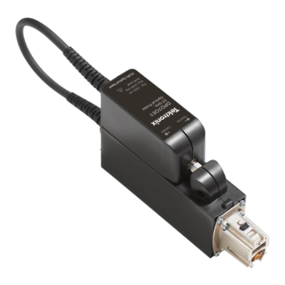
Do you have a question about the DPO7OE Series and is the answer not in the manual?

Questions and answers

Summary of Contents for Tektronix DPO7OE Series

  • Page 1 T h e t e s t & me a s u r e me n t e q u i p me n t y o u n e e d a t t h e p r i c e y o u w a n t . A l l t e s t I n s t r u me n t s , I n c .
  • Page 2 DPO7OE Series 33 GHz and 59 GHz Optical Probes User Manual *P071355801* 071-3558-01...
  • Page 4 The servicing instructions are for use by qualified personnel only. To avoid personal injury, do not perform any servicing unless you are qualified to do so. Refer to all safety summaries prior to performing service. This document supports DPO7OE Series software version 1.0 and above. www.tek.com 071-3558-01...
  • Page 5 Tektronix. All rights reserved. Licensed software products are owned by Tektronix or its subsidiaries or suppliers, and are protected by national copyright laws and international treaty provisions. Tektronix products are covered by U.S. and foreign patents, issued and pending. Information in this publication supersedes that in all previously published material.
  • Page 6 Tektronix, with shipping charges prepaid. Tektronix shall pay for the return of the product to Customer if the shipment is to a location within the country in which the Tektronix service center is located. Customer shall be responsible for paying all shipping charges, duties, taxes, and any other charges for products returned to any other locations.
  • Page 8: Table Of Contents

    Cleaning the exterior of the probe ....................Probe setup ........................... Vertical Setup settings ......................Probe Setup settings ........................ Calibration ............................ Dark level compensation ......................Signal path compensation ......................Optical filter and bandwidth settings .................... DPO7OE Series Optical Probes User Manual...
  • Page 9 ..................Optical reference receiver performance ..................Appendix A: Programming Interface (PI) commands CH<x>:OPTI:POWER? (query only) ..................CH<x>:OPTIcal:AOPstream ......................CH<x>:OPTIcal:RCVR ........................ CH<x>:OPTIcal:RCVR:USERVALue? (query only) ..............CH<x>:OPTIcal:WLENgth ......................CH<x>:OPTIcal:WLENgth:LIST? (query only) ................CH<x>:PRObe:GAIN? (query only) .................... DPO7OE Series Optical Probes User Manual...
  • Page 10: Software License Agreement

    2. Transfer the Program to any person or organization outside of Customer or the corporation of which Customer is a part without the prior written consent of Tektronix, except in connection with the transfer of the equipment within which the programs are encoded or incorporated;...
  • Page 11 Program may be used. Title to the Program and all copies thereof, but not the media on which the Program or copies may reside, shall be and remain with Tektronix or others for whom Tektronix has obtained a respective licensing right.
  • Page 12 POSSIBILITY OF SUCH DAMAGES. THIRD-PARTY DISCLAIMER. Except as expressly agreed otherwise, third parties from whom Tektronix may have obtained a licensing right do not warrant the program, do not assume any liability with respect to its use, and do not undertake to furnish any support or information relating thereto.
  • Page 13 Software license agreement DPO7OE Series Optical Probes User Manual...
  • Page 14: Important Safety Information

    Before use, always check the product with a known source to be sure it is operating correctly. This product is not intended for detection of hazardous voltages. DPO7OE Series Optical Probes User Manual...
  • Page 15: Service Safety Summary

    Do not service alone. Do not perform internal service or adjustments of this product unless another person capable of rendering first aid and resuscitation is present. Verify safety after repair. Always recheck ground continuity and mains dielectric strength after performing a repair. viii DPO7OE Series Optical Probes User Manual...
  • Page 16: Terms In The Manual

    (This symbol may also be used to refer the user to ratings in the manual.) The following symbols may appear on the product: DPO7OE Series Optical Probes User Manual...
  • Page 17 Important safety information DPO7OE Series Optical Probes User Manual...
  • Page 18: Compliance Information

    This section lists the environmental standards with which the instrument complies. Questions about the following compliance information may be directed to the following address: Tektronix, Inc. PO Box 500, MS 19‐045 Beaverton, OR 97077, USA www.tek.com Environmental compliance This section provides information about the environmental impact of the product.
  • Page 19 Compliance Information DPO7OE Series Optical Probes User Manual...
  • Page 20: Preface

    Appendix A describes the Programming Interface (PI) commands. ■ Where to find more information The DPO7OE series probes are used as part of a larger instrument system. Measurement, calibration, and other settings are set from the main instrument controls. See the oscilloscope Help and documentation for information on setting up and taking measurements, instrument specifications, programming commands, and performance verification procedures.
  • Page 21 Learn how to Technical Reference perform performance verification procedures on warranted specifications This reference shows the DPO7OE Series PDF on www.tek.com/manuals memory devices in the product Declassification and Security and provides sanitize and Instructions removal procedures DPO7OE Series Optical Probes User Manual...
  • Page 22: Getting Started

    100 Gb/s (DPO7OE1) and 400 Gb/s (DPO7OE2) telecommunication or data communication signals. The DPO7OE Series can be used in conjunction with 50 GHz and higher ATI channels on the DPO70000SX instruments, providing ample bandwidth for a smooth BT response for up to 28 GBd data.
  • Page 23 Getting started Figure 1: DPO7OE Series optical probe with shuttle attached to carrier Figure 2: DPO7OE Series with shuttle detached from carrier DPO7OE Series Optical Probes User Manual...
  • Page 24: Key Features

    ATI channel, or channels with the TekConnect interface. This versatility makes these optical probes suitable for use with all DPO70000SX, MSO/DPO70000DX, and MSO/DPO70000C series oscilloscopes. Figure 3: DPO7OE Series supports multiple optical inputs and multi-carrier configurations All DPO7OE Series optical probes are custom configured, high-bandwidth Key features optical acquisition modules suitable for use in a variety of test and measurement applications and systems.
  • Page 25: Options And Accessories

    The following product options are available: NOTE. Select an optical input connector type from the following mandatory, mutually exclusive options. One of these options must be ordered when you purchase a DPO7OE Series Optical Probe. DPO7OE Series Optical Probes User Manual...
  • Page 26 The following optional accessory is available: Accessory Tektronix part number Optical connector cleaner 006-8327-xx Option FC/APC limits the probe responsiveness to the following wavelength ranges: DPO7OE1 is 1260 nm to 1650 nm; DPO7OE2 is 1200 nm to 1650 nm. DPO7OE Series Optical Probes User Manual...
  • Page 27: Required And Recommended Oscilloscope Software

    Figure 4: Hard case accessory Required and recommended oscilloscope software Required oscilloscope The DPO7OE Series optical probes are compatible with all DPO70000SX, MSO/ software version DPO70000DX, and MSO/DPO70000C Series oscilloscopes. To use the probe, these oscilloscopes must be running one of the following firmware versions: 70 GHz oscilloscope models: Version 10.8.0 or later.
  • Page 28: Installation

    Getting started Recommended The DPO7OE Series probes enable deep analysis of PAM4 and PAM2 (NRZ) oscilloscope application signaling by using the following Tektronix DPOJET Jitter and Eye Analysis and software PAM4 Analysis software installed on the oscilloscope. Application software Description...
  • Page 29: Tekconnect Probe Installation

    Getting started TekConnect probe The following procedure describes how to connect the DPO7OE Series probe to the oscilloscope. installation Figure 5: Connecting the DPO7OE Series probe to the oscilloscope 1. Remove the probe from the hard case. 2. If necessary, attach the probe shuttle to the carrier: a.
  • Page 30: Ati Channel Installation

    Getting started ATI channel installation The following procedure describes how to connect the DPO7OE Series probe shuttle to an ATI channel on the oscilloscope. Before you install the probe shuttle on the ATI channel, install the probe on the oscilloscope TekConnect Channel 1. See TekConnect probe installation page 8.
  • Page 31 6. Tighten the nut on the shuttle counter-clockwise (left) using a torque wrench set to 8 in-lbs. to secure the shuttle to the ATI bracket. Once the probe shuttle has been connected to the oscilloscope, the probe will be automatically detected by the system. DPO7OE Series Optical Probes User Manual...
  • Page 32: First Turn On Functional Checks

    Getting started First turn on functional checks 1. When a DPO7OE Series probe is plugged into a 70k series oscilloscope for the first time, measured S-parameters for the probe are copied from the probe internal memory to build custom correction filters. The message pictured below appears on the screen while this process takes place.
  • Page 33 5. Select Vertical > Probe Cal to open the Probe Setup panel. Select the tab for the channel that the probe is attached to. 6. Press the Properties button. The Probe Properties window is displayed. 7. Verify the probe model number and serial number. DPO7OE Series Optical Probes User Manual...
  • Page 34: Operating Basics

    To prevent loss of optical power or damage to the optical connectors, keep the connectors clean at all times. Check that all connectors and protective caps are clean before connecting them to the probe. See Cleaning optical connectors page 17. DPO7OE Series Optical Probes User Manual...
  • Page 35: Connecting Optical Signals To The Probe

    Interchanging these connections can potentially damage the optical input of the probe. If you connect fiber cores larger than the maximum diameter for the probe model, the O/E converters may still couple light, but the mismatch in core diameter will cause lower conversion gain. DPO7OE Series Optical Probes User Manual...
  • Page 36 3. Using finger pressure only, firmly tighten the cable connector or the adapter shell. Once the fiber optic cable has been connected to the probe, the oscilloscope will be ready to perform measurements on the cable signal. DPO7OE Series Optical Probes User Manual...
  • Page 37: Attenuating Optical Signals

    An additional optical module function that you control from the main instrument is external channel attenuation. External Attenuation lets you enter a number representing any external attenuation you have added to a channel. DPO7OE Series Optical Probes User Manual...
  • Page 38: Cleaning Optical Connectors

    Required supplies Use the following supplies to clean optical connectors: Dry, clean, and dust-free compressed air (such as Tektronix part number ■ 118-1068-xx) FIS cassette cleaner (such as FI-6270) and/or FIS tape dispenser cleaner ■...
  • Page 39 Lift up on the JAE connector latch and pull the connector away from the probe. This exposes the male fiber end-face behind the JAE connector. Figure 10: Removing the JAE connector from the probe DPO7OE Series Optical Probes User Manual...
  • Page 40 7. Use a cleaning cloth to clean the end-face of the input fiber or device that you attach to the JAE connector input. NOTE. Use a similar cleaning method to clean the fiber end-face input fiber or device. DPO7OE Series Optical Probes User Manual...
  • Page 41: Cleaning The Exterior Of The Probe

    Use a 75% isopropyl alcohol solution as a cleaner and rinse with deionized water. Before using any other type of cleaner, consult your Tektronix Service Center or representative. Do not open the case of the probe. There are no user serviceable components and cleaning the interior is not required.
  • Page 42 12. Use the Deskew and Attenuation controls to compensate for propagation delays of different length signal cable and probe combinations and to set the input/output ratio of any external attenuation or gain between the signal and input channels. DPO7OE Series Optical Probes User Manual...
  • Page 43: Vertical Setup Settings

    ■ Logic Properties. Click Logic Properties when you want to specify the voltage threshold level(s) of the Ch1-Ch4 (live) and M1-M4 (math) channels to use as logic waveforms and to include in a bus. DPO7OE Series Optical Probes User Manual...
  • Page 44 DSP. It then enables DSP and selects the appropriate bandwidth. ■ Click Analog Only to disable Bandwidth Enhancement and return to Analog operation. The Bandwidth drop-down list adds (HW) to the selection indicating a hardware/analog-only filter. DPO7OE Series Optical Probes User Manual...
  • Page 45 Vertical Setup controls. ■ Probe Cal. Click the Probe Cal button to open the Probe Setup screen where you can perform probe compensation. See Probe Setup settings on page 28. DPO7OE Series Optical Probes User Manual...
  • Page 46 Probe Controls. Click the Probe Controls button to open the Probe Controls screen shown below. Figure 13: Probe Controls screen ■ Vertical Zoom. Click Vertical Zoom to enable MultiView Zoom, which allows you to use the Multipurpose knobs to zoom in on the waveform. DPO7OE Series Optical Probes User Manual...
  • Page 47 4. Select the slope and level for each channel. 5. Wait for a sufficient population to be accumulated (the indicator near the To Mean button turns green). Figure 14: Example of initial deskewed waveform 6. Press the To Mean button. DPO7OE Series Optical Probes User Manual...
  • Page 48 7. Repeat steps 4 through 6 multiple times. Since the difference in resolution between ps and fs is large, the first deskew attempt gets you close and the second attempt gets into the fs range. Figure 15: Example of final deskewed waveform DPO7OE Series Optical Probes User Manual...
  • Page 49: Probe Setup Settings

    See Dark level compensation on page 32. ■ Add User Wavelength. Click Add User Wavelength to create a custom wavelength, which will be added to the list of standard Wavelength DPO7OE Series Optical Probes User Manual...
  • Page 50 BW option, an entry box appears, as shown above, where you can enter a custom frequency. See Bandwidth for the Flat filter settings on page 42. See Bandwidth for the ORR filter settings page 42. DPO7OE Series Optical Probes User Manual...
  • Page 51 4. After you enter the Wavelength and Reference Power values, click Compensate Go. A message appears while the oscilloscope computes the correct gain. 5. Click OK to save the calculated wavelength and gain. DPO7OE Series Optical Probes User Manual...
  • Page 52 Operating basics 6. The Probe Setup screen will now show an additional User Cal'd radio button with a drop-down list of all user wavelengths. DPO7OE Series Optical Probes User Manual...
  • Page 53: Calibration

    Precise optical measurements require that a dark level compensation has been done beforehand. Dark level compensation measures the average DC output of the DPO7OE Series when no light is present at the optical input. This measured value is then subtracted from all sampled values.
  • Page 54 Temperature Status is Ready. This typically takes 20 minutes to an hour depending on the oscilloscope model. ■ All channel input signals must be removed. ■ If the timebase external reference mode is selected, leave the external reference signal connected and active. DPO7OE Series Optical Probes User Manual...
  • Page 55 Operating basics 2. Select Instrument Calibration. Figure 18: Utility menu on DPO70000 oscilloscopes DPO7OE Series Optical Probes User Manual...
  • Page 56 If you use a drive that has not had SPC run while in the current instrument, you will see a no prior SPC warning message. If you see this warning, run SPC. Figure 19: Calibration menu on DPO70000 oscilloscopes DPO7OE Series Optical Probes User Manual...
  • Page 57 30 days since SPC was last run. ■ Red indicates that SPC needs to be run (the temperature has varied more than 5 °C, SPC failed, or SPC has not been run). DPO7OE Series Optical Probes User Manual...
  • Page 58 The operating temperature is not within 5 °C of the previous signal path compensation. Warming up The instrument has not warmed up. Wait for the instrument to complete its warm up period before running the signal path compensation procedure. DPO7OE Series Optical Probes User Manual...
  • Page 59: Optical Filter And Bandwidth Settings

    Maximum bandwidth is limited on TekConnect channels to the maximum allowed by the oscilloscope channel ORR compliance is modulation type dependent. Compliance can be achieved on ATI channels for NRZ rates up to 39 GBd and PAM4 rates up to 59 GBd. DPO7OE Series Optical Probes User Manual...
  • Page 60: Electrical Output

    The figure below shows a waveform exceeding the dynamic range of the channel and the overload indicator turned on. Figure 21: Overload indicator DPO7OE Series Optical Probes User Manual...
  • Page 61: Correcting For Conversion Gain

    Add User Wavelength window). Conversion gain has units of V/W. The channel waveform is corrected by dividing the sampled voltage output of the O/E converter by the conversion gain for the wavelength selected in the Probe Setup menu. DPO7OE Series Optical Probes User Manual...
  • Page 62: Reference

    (BWe). The electrical bandwidth is the frequency f at which the following equation is satisfied: − 3 dBe = 20 log( DPO7OE Series Optical Probes User Manual...
  • Page 63: Bandwidth For The Flat Filter Settings

    Ideal BT4 filters are created for each filter bandwidth and applied to the flattened response of the O/E. Thus, if the flattening Finite Impulse Response (FIR) filter is working correctly, then all filter settings for that wavelength will work correctly. DPO7OE Series Optical Probes User Manual...
  • Page 64: Optical Reference Receiver Performance

    50% of the symbol rate. The ORR BT4 filters for the important symbol rates of PAM4 standards, such as 53.152 GBd and 26.5625 GBd, are also available in the DPO7OE Series. Acquiring signals on a high-bandwidth ATI channel maintains linear phase across the passband of the channel.
  • Page 65 Reference The smooth, controlled system response with the DPO7OE Series and DPO70000SX oscilloscope is possible because the oscilloscope's system software calculates the BT4 filters using the S-parameters unique to the optical probe and the oscilloscope channel. Most real-time oscilloscopes today have a rather sharp roll-off (e.g.
  • Page 66: Appendix A: Programming Interface (Pi) Commands

    This command queries the power meter reading of the DPO7OE Series probe attached to the specified channel. Group Vertical Syntax CH<x>:OPTI:POWER? Returns Returns the power meter reading of the DPO7OE Series probe attached to the specified channel. DPO7OE Series Optical Probes User Manual...
  • Page 67: Ch:Optical:aopstream

    ON indicates that streaming of Average Output Power is set to on. Examples CH1:OPTI:AOPstream ON sets the streaming of Average Output Power to CH1:OPTI:AOPstream? might return OFF, indicating that streaming of Average Output Power is set to off. DPO7OE Series Optical Probes User Manual...
  • Page 68: Ch:Optical:rcvr

    <NR1> is the baud rate. Units are in Baud. Examples CH1:OPTIcal:RCVR FLAT33 sets the DSP filter to FLAT33. CH1:OPTI:RCVR USER, 28.6E9 sets the DSP filter to 28.6 GBd User filter. CH1:OPTIcal:RCVR? might return FLAT, indicating the DSP filter is set to FLAT. DPO7OE Series Optical Probes User Manual...
  • Page 69: X>:Optical:rcvr:uservalue? (Query Only)

    User Wavelength Gain Compensation window from the UI. Once the value is loaded, it can be recalled using this command. FACTory specifies using factory calibration values. The second argument defaults to FACTory if none is specified. DPO7OE Series Optical Probes User Manual...
  • Page 70: X>:Optical:wlength:list? (Query Only)

    For example, a common 10x probe has a gain of 0.1. Group Vertical Syntax CH<x>:PRObe:GAIN? Examples CH2:PROBE:GAIN? might return :CH2:PROBE:GAIN 0.1000E+00, indicating that the attached 10X probe delivers 0.1 V to the Channel 2 BNC for every 1.0 V applied to the probe input. DPO7OE Series Optical Probes User Manual...
  • Page 71 Appendix A: Programming Interface (PI) commands DPO7OE Series Optical Probes User Manual...

This manual is also suitable for:

Dpo7oe2

Table of Contents