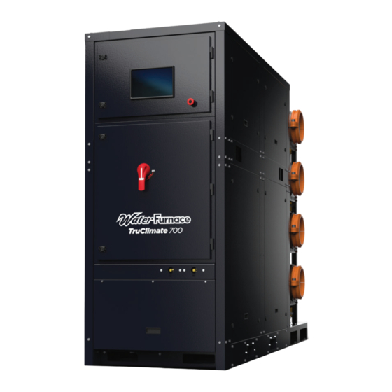
WaterFurnace TruClimate 700 Installation Manual
Commercial 60 hz water-cooled chiller
Hide thumbs
Also See for TruClimate 700:
- Installation manual (48 pages) ,
- Operation & maintenance manual (82 pages)
Table of Contents
Advertisement
Quick Links
Commercial 60 Hz
Water-Cooled Chiller
• R-513A Refrigerant
• 90-140 Ton Lead Variable Speed Compressor
Installation Information
Installation Information
Water Piping Connections
Water Piping Connections
Electrical Data
Electrical Data
Microprocessor Control
Microprocessor Control
Startup Procedures
Startup Procedures
Preventive Maintenance
Preventive Maintenance
IM1904WW 05/23
Advertisement
Table of Contents

Related Manuals for WaterFurnace TruClimate 700


Summary of Contents for WaterFurnace TruClimate 700
- Page 1 Commercial 60 Hz Water-Cooled Chiller • R-513A Refrigerant • 90-140 Ton Lead Variable Speed Compressor Installation Information Installation Information Water Piping Connections Water Piping Connections Electrical Data Electrical Data Microprocessor Control Microprocessor Control Startup Procedures Startup Procedures Preventive Maintenance Preventive Maintenance IM1904WW 05/23...
-
Page 3: Table Of Contents
TruClimate 700 Features........ -
Page 4: General Installation Information
TRUCLIMATE 700 90-140 TON INSTALLATION MANUAL General Installation Information Safety Considerations acknowledging the damage. Units are to be stored in a location that provides adequate protection from dirt, debris This appliance is not intended for use by persons and moisture. -
Page 5: Model Nomenclature
Sound Kit Option Control Option B – Cabinet Sound D – Primary Unit (Master Controller) Electrical Availability Voltage Dual Variable Speed 208-230/60/3 ● ● ● 460/60/3 575/60/3 3/16/23 All TruClimate 700 90-140 Ton product is Safety listed under UL1995 thru ETL... -
Page 6: Hydrolink Supervisory Control Nomenclature
TRUCLIMATE 700 90-140 TON INSTALLATION MANUAL HydroLink Supervisory Control Nomenclature (Accessory) 9-10 Family Vintage HSC – HydroLink Supervisory Control B – Current Chiller Module Non-Standard Option N – NXW – Compact Scroll Details D – WC – Dual Scroll Modular Chiller SS –... -
Page 7: Truclimate 700 Features
TRUCLIMATE 700 90-140 TON INSTALLATION MANUAL The TruClimate 700 Features Color touch screen chiller interface Standard Aurora Hydrolink microprocessor provides easy-to-use instant access controls include set-point control, advanced to unit performance refrigeration monitoring, a standard color touch-screen interface, advanced trending... - Page 8 TRUCLIMATE 700 90-140 TON INSTALLATION MANUAL The TruClimate 700 Features cont. Variable speed drive DC Inverted Variable Factory installed Removable 4-pipe integrated with Speed Single Screw flow switches header rack Compressor compressor provides and modulating isolation valves envelope control for improved reliability 8 [in.] Grooved SCH40...
- Page 9 The TruClimate 700 Features cont. The True "Modular" Concept Most modular chillers can be ganged together but once in place cannot be easily serviced or removed. WaterFurnace modular screw units feature several industry firsts to provide a true modular chiller! Modular chiller unit can be removed from the bank and replaced with a new unit using strategically placed fork truck pockets.
-
Page 10: Dimensional Data
TRUCLIMATE 700 90-140 TON INSTALLATION MANUAL Dimensional Data:... - Page 11 TRUCLIMATE 700 90-140 TON INSTALLATION MANUAL Dimensional Data: Service Clearance...
- Page 12 TRUCLIMATE 700 90-140 TON INSTALLATION MANUAL Dimensional Data: Center of Gravity...
- Page 13 TRUCLIMATE 700 90-140 TON INSTALLATION MANUAL Dimensional Data: Rigging Data...
-
Page 14: Chiller Installation
TRUCLIMATE 700 90-140 TON INSTALLATION MANUAL Chiller Installation Unpack and inspect unit and pipe rack. Note and photograph any damage that is visible. Check for: panel damage tight frame bolts pipe rack damage secure headers loose victaulic connections on header racks... - Page 15 TRUCLIMATE 700 90-140 TON INSTALLATION MANUAL Chiller Installation cont. Remove (4) u-bolts (image below) and retain for later installation. Remove (4) U-bolts Remove (4) pipes that are attached to the pipe rack in shipment (image below). Remove (4) sections of pipe...
- Page 16 TRUCLIMATE 700 90-140 TON INSTALLATION MANUAL Chiller Installation cont. Place removed pipes into the main unit’s heat exchangers, attach victaulic connections that were previously removed. Using a forklift move main unit into position, carefully guiding pipes from heat exchangers into the pipe rack.
- Page 17 TRUCLIMATE 700 90-140 TON INSTALLATION MANUAL Chiller Installation cont. 10. Install bolts along the junction of pipe rack frame and unit body. Attach the quick connect isolation valves and flow switches.
-
Page 18: Removing A Module From The Bank Of Units
TRUCLIMATE 700 90-140 TON INSTALLATION MANUAL Removing Module from Bank of Units Undo the 2.5” groove couplings, disconnect all 3-way valve harnesses and isolation valve harnesses, u-bolts and victaulic connections (detailed in installation section). Remove bolts attaching the pipe rack to the unit frame (see image) Slightly lift (2in maximum) the module and pull away from the bank. -
Page 19: Lifting And Short Distance Transport
TRUCLIMATE 700 90-140 TON INSTALLATION MANUAL Lifting and Short Distance Transport When lifting the chiller all lifting brackets must be used. 2. Always use spreader bars. The sound enclosure of the chiller may be damaged if spreader bars are not used. -
Page 20: Water Quality
TRUCLIMATE 700 90-140 TON INSTALLATION MANUAL Water Quality 1.0. Minimum Fluid Volume 1.4. Flow Sensing Devices Water-to-water heat pumps require a minimum amount A fl ow switch or equivalent must be installed on the of source and load side fl uid volume to ensure accurate evaporator for each unit to be installed. - Page 21 TRUCLIMATE 700 90-140 TON INSTALLATION MANUAL Water Quality cont. 1.6. Insulation 1.7. Brine Applications Chillers are built with factory installed insulation on any Applications where the leaving fl uid temperature goes surface that may be subject to temperatures below the below 40°F a suitable brine solution must be used.
-
Page 22: Water Connections
TRUCLIMATE 700 90-140 TON INSTALLATION MANUAL Water Connections Water Piping must be installed in accordance with Temperature headers application codes and per necessary standards. Supply Temperature headers will need to be installed between the and return connections should be connected per units’... -
Page 23: Electrical Data
TRUCLIMATE 700 90-140 TON INSTALLATION MANUAL Electrical Data Compressor Total Voltage Model Rated Voltage Unit Circ Fuse/ Min/Max LRA1 HACR 460/60/3 414/506 190.0 156.0 20.0 156.0 195.0 460/60/3 414/506 225.0 185.0 20.0 185.0 231.3 460/60/3 414/506 290.0 240.0 20.0 240.0 300.0... -
Page 24: Electrical System And Controls - Safety Circuit
TRUCLIMATE 700 90-140 TON INSTALLATION MANUAL Electrical System and Controls - Safety Circuit Chiller Safety Circuit • Safe Torque Off (STO) stantaneous Lock-Out • “motor-off” function. • Inverter (VFD) is powered anytime the chiller power is on. • STO is wired to the compressor contactor (CC) output of the Aurora control. - Page 25 TRUCLIMATE 700 90-140 TON INSTALLATION MANUAL Wiring Schematic (next page)
-
Page 26: Wiring Schematics
TRUCLIMATE 700 90-140 TON INSTALLATION MANUAL Wiring Schematics Reactor A Cooling Fan Black (108) Black (107) Blue (106) White Black Blue (105) Grey (104) Grey (103) Black (318) Yellow( 102 ) White (317) Yellow( 101 ) Blue Jumper (142) Blue (021) - Page 27 TRUCLIMATE 700 90-140 TON INSTALLATION MANUAL Wiring Schematics cont. Legend Blue (011) Yellow (013) GROUND THERMISTER RELAY CONTACTS- PRESSURE NO,NC TRANSDUCER JUNCTION POINT FUSE SCREW CONNECTOR TEMP SENSOR Yellow (024) LPS-LOW PRESSURE SWITCH Black (022) HPS-HIGH PRESSURE SWITCH Black POWER SUPPLY...
-
Page 28: Hydrolink2 Aurora Chiller Controls
TRUCLIMATE 700 90-140 TON INSTALLATION MANUAL HydroLink2 Aurora Chiller Controls Overview HydroLink2 Control The HydroLink2 Control is a Niagara control that functions The HydroLink2 Aurora Control is the ultimate chiller control as a master control communicating to ABC “A” via Modbus system that accurately controls fluid temperatures while protocol. - Page 29 TRUCLIMATE 700 90-140 TON INSTALLATION MANUAL HydroLink2 Aurora Chiller Controls cont. Software Features Field Selectable Options via Hardware DIP Switch (SW1) – Test/Configuration Button (See SW1 Safety Features Operation Table) The following safety features are provided to protect the compressor, heat exchangers, wiring and other components...
- Page 30 TRUCLIMATE 700 90-140 TON INSTALLATION MANUAL HydroLink2 Aurora Chiller Controls cont. Freeze Detection - Refrigerant (Condenser – E5 or Operation Description Evaporator HX E4) – Freeze detection can be triggered by Power Up - The unit will not operate until all the inputs and either a 30 sec.
- Page 31 TRUCLIMATE 700 90-140 TON INSTALLATION MANUAL HydroLink2 Aurora Chiller Controls cont. Other Modes of Operation HydroLink2 Aurora in BAS Applications Emergency Shutdown - Four (4) seconds after a valid ES The HydroLink2 Aurora is designed to allow chillers to be...
- Page 32 TRUCLIMATE 700 90-140 TON INSTALLATION MANUAL HydroLink2 Aurora Chiller Controls cont. HydroLink2 Aurora Features HydroLink2 Aurora Touch Interface • Built-in surge transient protection circuitry Utilizing a 10” color touch-screen interface, the HydroLink2 • Operating range of -20° to 140°F [-28.9°C to 60°C]; 10 to...
- Page 33 TRUCLIMATE 700 90-140 TON INSTALLATION MANUAL HydroLink2 Aurora Chiller Controls cont. Fault, Configuration and Status Codes Fault Reset/ Fault Flash Lockout Fault Condition Summary Code Remove Code * Normal - No Faults Fault-Input Auto Tstat input error. Autoreset upon condition removal.
- Page 34 TRUCLIMATE 700 90-140 TON INSTALLATION MANUAL HydroLink2 Aurora Chiller Controls cont. Other User Defined Field I/O Field Relay 7 – This shows the state of the Field Relay 7 on AXB A (labeled K6). When Field Relay is “ON” the Field Relay Field Temp 1 - Can display the temperature of a field supplied 7 will be engaged.
-
Page 35: Controls And Bas Integration
TRUCLIMATE 700 90-140 TON INSTALLATION MANUAL Controls and BAS Integration Operation and Connection Master Panel Connections With a DDC device the chiller may be controlled by a If a master panel is present, then the BAS will only connect building management system. The DDC device can work... -
Page 36: Evaporator Pressure Drop
TRUCLIMATE 700 90-140 TON INSTALLATION MANUAL Evaporator Pressure Drop... -
Page 37: Condenser Pressure Drop
TRUCLIMATE 700 90-140 TON INSTALLATION MANUAL Condenser Pressure Drop... -
Page 38: Start-Up Data Collection
TRUCLIMATE 700 90-140 TON INSTALLATION MANUAL Start-Up Data Collection Data Collection is to be schedule and implemented by a qualified representative. Prior to Powering Up Machine Suction Temperature Discharge Pressure Super Heat Hx1 Gas Pressure Subcooling Hx1 Sat Capacity Hx2 Gas Pressure... -
Page 39: Screw Refrigeration Cycle Analysis
TRUCLIMATE 700 90-140 TON INSTALLATION MANUAL Screw Refrigeration Cycle Analysis... -
Page 40: Reference Calculations, Legend, And Unit Startup
TRUCLIMATE 700 90-140 TON INSTALLATION MANUAL Reference Calculations Heating Calculations: Cooling Calculations: LWT = EWT - LWT = EWT + GPM x 500* GPM x 500* NOTE: * When using water. Legend Abbreviations and Definitions LWT = Leaving Water Temperature... -
Page 41: Preventative Maintenance
TRUCLIMATE 700 90-140 TON INSTALLATION MANUAL Preventative Maintenance Unit Heat Exchanger Maintenance Replacement Procedures Keep all air out of the water or antifreeze solution. When contacting the company for service or Keep the system under pressure at all times. Closed... -
Page 42: Troubleshooting
TRUCLIMATE 700 90-140 TON INSTALLATION MANUAL Screw Chiller Troubleshooting Form Company Name: _________________________________ Company Phone No: ______________________________ Technician Name: ________________________________ Date: __________________________________________ Model No: ______________________________________ Serial No:_______________________________________ Owner’s Name: __________________________________ Open or Closed Loop: _____________________________ Installation Address: ______________________________ Installation Date: _________________________________... -
Page 43: Chiller Start-Up Report
TRUCLIMATE 700 90-140 TON INSTALLATION MANUAL Chiller Start-up Report PRELIMINARY CHECKS INSPECTION ITEM RESULT INITIALS INSPECT UNIT FOR SHIPPING OR INSTALLATION DAMAGE VERIFY UNIT IS LEVEL INSPECT WATER PIPING FOR PROPER INSTALLATION, AND THAT PIPING IS INSULATED ADEQUATELY INSPECT INSIDE OF UNIT FOR POSSIBLE REFRIGERANT,... - Page 44 TRUCLIMATE 700 90-140 TON INSTALLATION MANUAL Chiller Start-up Report cont. PRELIMINARY CHECKS CONT. INSPECTION ITEM RESULT INITIALS (GPM) SOURCE FLOW RATE GEO FLOW RATE (PSI) EVAPORATOR (LOAD) PRESSURE DROP EVAPORATOR PRESSURE DROP (PSI) CONDENSER (SOURCE) PRESSURE DROP CONDENSER PRESSURE DROP...
- Page 45 TRUCLIMATE 700 90-140 TON INSTALLATION MANUAL Chiller Start-up Report cont. CONTROLS CHECKS INSPECTION ITEM RESULT INITIALS POWER ON INTERFACE AND ENSURE ALL PAGES AND DATA IS READING NORMALLY VERIFY USER MANAGEMENT IS SETUP PROPERLY (ENHANCED CONTROLS ONLY) VERIFY WATER TEMPERATURES CLOSELY MATCH REFRIGERANT SAT.
- Page 46 TRUCLIMATE 700 90-140 TON INSTALLATION MANUAL Chiller Start-up Report cont. RUN CHECKS INSPECTION ITEM RESULT INITIALS VERIFY COMPRESSOR OIL LEVEL (˚F) MODE (˚F) ENTERING HOT WATER TEMP (˚F) LEAVING HOT WATER TEMP (˚F) ENTERING COLD WATER TEMP (˚F) LEAVING COLD WATER TEMP...
-
Page 47: Revision Guide
TRUCLIMATE 700 90-140 TON INSTALLATION MANUAL Revision Guide Pages: Description: Date: 13 April 2023 Document Creation... - Page 48 90-140 Tons Document: Installation Manual IM1904WW 05/23 ©2023 WaterFurnace International, Inc., 9000 Conservation Way, Fort Wayne, IN 46809-9794. WaterFurnace has a policy of continual product research and development and reserves the right to change design and specifi cations without notice.
Need help?
Do you have a question about the TruClimate 700 and is the answer not in the manual?
Questions and answers