Table of Contents
Advertisement
Quick Links
Operator's Manual
VANTAGE
Register your machine:
www.lincolnelectric.com/register
Authorized Service and Distributor Locator:
www.lincolnelectric.com/locator
Save for future reference
Date Purchased
Code: (ex: 10859)
Serial: (ex: U1060512345)
IM10207-D
| Issue D ate May-21
© Lincoln Global, Inc. All Rights Reserved.
®
400-I
For use with machines having Code Numbers:
12366, 12509, 12636,
12691,13199
Need Help? Call 1.888.935.3877
to talk to a Service Representative
Hours of Operation:
8:00 AM to 6:00 PM (ET) Mon. thru Fri.
After hours?
Use "Ask the Experts" at lincolnelectric.com
A Lincoln Service Representative will contact
you
no later than the following business day.
For Service outside the USA:
Email: globalservice@lincolnelectric.com
Advertisement
Table of Contents

Related Manuals for Lincoln Electric VANTAGE 400-I


Summary of Contents for Lincoln Electric VANTAGE 400-I
- Page 1 Operator’s Manual VANTAGE ® 400-I For use with machines having Code Numbers: 12366, 12509, 12636, 12691,13199 Need Help? Call 1.888.935.3877 Register your machine: to talk to a Service Representative www.lincolnelectric.com/register Authorized Service and Distributor Locator: Hours of Operation: www.lincolnelectric.com/locator 8:00 AM to 6:00 PM (ET) Mon. thru Fri. Save for future reference After hours? Use “Ask the Experts”...
- Page 2 THANK YOU FOR SELECTING A QUALITY PRODUCT BY KEEP YOUR HEAD OUT OF THE FUMES. DON’T get too close to the arc. LINCOLN ELEC TRIC. Use corrective lenses if necessary to stay a reasonable distance away from the arc. READ and obey the Safety Data PLEASE EXAMINE CARTON AND EQUIPMENT FOR Sheet (SDS) and the warning label DAMAGE IMMEDIATELY...
- Page 3 W117.2-1974. A Free copy of “Arc Welding Safety” booklet E205 is available from the Lincoln Electric Company, 2.d. All welders should use the following procedures in order to 22801 St. Clair Avenue, Cleveland, Ohio 44117-1199.
- Page 4 SAFETY ELECTRIC SHOCK ARC RAYS CAN BURN. CAN KILL. 3.a. The electrode and work (or ground) circuits are 4.a. Use a shield with the proper filter and cover plates to protect your electrically “hot” when the welder is on. Do eyes from sparks and the rays of the arc when welding or not touch these “hot”...
- Page 5 SAFETY WELDING AND CUTTING CYLINDER MAY EXPLODE IF SPARKS CAN CAUSE DAMAGED. FIRE OR EXPLOSION. 7.a. Use only compressed gas cylinders containing the correct shielding gas for the process used 6.a. Remove fire hazards from the welding area. If and properly operating regulators designed for this is not possible, cover them to prevent the welding sparks the gas and pressure used.
-
Page 6: Table Of Contents
Machine Grounding..........................A-6 Welding Terminals..........................A-6 Welding Output Cables ..........................A-7 Cable Installation .............................A-7 Auxiliary Power .............................A-7 Standby Power Connections..........................A-7 Connection of Lincoln Electric Wire Feeders ....................A-8, A-9 _________________________________________________________________________________________ Operation Section B Safety Precautions ............................B-1 General Description............................B-1 For Auxiliary Power ............................B-1 Engine Operation............................B-1 Add Fuel ...............................B-1... - Page 7 TABLE OF CONTENTS Page Maintenance ..........................Section D Safety Precautions........................D-1 Routine Maintenance ........................D-1 Engine Service Items ........................D-1 Engine Oil Change ......................D-1, D-2 Engine Oil Filter Change .......................D-2 Air Cleaner ...........................D-2 Service Instructions And Installation Tips for Engine Air Filter ..........D-3 Cooling System..........................D-4 Tightening the Fan Belt ......................D-4 Fuel .............................D-4 Bleeding the Fuel System.....................D-4...
-
Page 8: Installation
VANTAGE ® 400-I INSTALLATION TECHNICAL SPECIFICATIONS - VANTAGE 400-I (K4169-1) ® INPUT - DIESEL ENGINE Make/Model Description Horsepower Capacities Operating Displacement cu. in. (ltrs.) Starting Systems @ 1800 RPM Speed (RPM) Bore x Stroke inch (mm) 12VDC Battery High Fuel: 20gal.(75.7L) and starter 1890 RPM Oil: 6.4qts.(6.0L) -
Page 9: Machine Specifications
VANTAGE ® 400-I INSTALLATION MACHINE SPECIFICATIONS RECEPTACLES AUXILIARY POWER CIRCUIT BREAKER OTHER CIRCUIT BREAKERS (1) 220V Euro Style (1) 16Amp for Single Phase and 3-Phase (3-pole) 10AMP for Engine Battery (1) 380V Euro Style Charging Circuit 10AMP for 42V Wire Feeder Power... -
Page 10: Safety Precautions
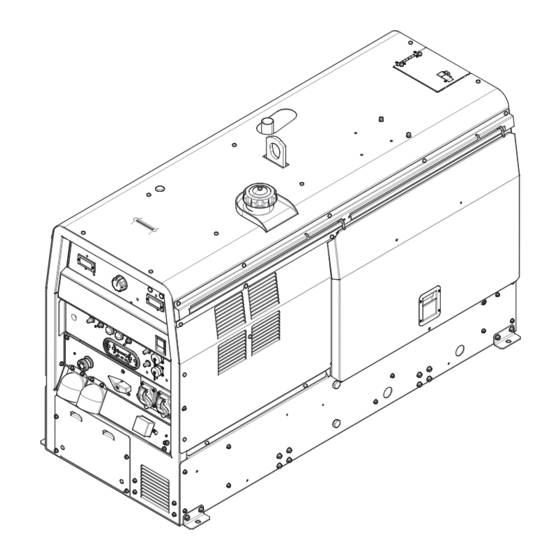
VANTAGE ® 400-I INSTALLATION SAFETY PRECAUTIONS FIGURE A.1 WARNING (VRD)-VOLTAGE REDUCTION DEVICE SWITCH IS LOCATED IN THIS AREA. Do not attempt to use this equipment until you have thoroughly read the engine manufacturer’s manual supplied with your welder. It includes important safety precautions, detailed engine starting, operating and maintenance instructions, and parts lists. -
Page 11: Lifting
VANTAGE ® 400-I INSTALLATION LIFTING TOWING The VANTAGE ® 400-I weighs approximately 1190 lbs. (540kg.) with a full tank of fuel (1035 lbs. (470kg.) less fuel). A lift bail is Use a recommended trailer for use with this equipment for road, in-plant mounted to the machine and should and yard towing by a vehicle(1). -
Page 12: Pre-Operation Engine Service
VANTAGE ® 400-I INSTALLATION PRE-OPERATION ENGINE SERVICE ENGINE COOLING SYSTEM READ the engine operating and maintenance instructions sup- plied with this machine. WARNING WARNING Air to cool the engine is drawn in the side and exhausted through radiator & case back. It is •... -
Page 13: Remote Control
VANTAGE ® 400-I INSTALLATION ELECTRICAL CONNECTIONS REMOTE CONTROL The VANTAGE ® 400-I is equipped with a 6-pin and a 14-pin con- nector. When in the Arc Gouging or CV-WIRE modes and when a MACHINE GROUNDING remote control is connected to the 6-pin Connector, the Because this portable engine driven welder creates its own auto-sensing circuit automatically switches the OUTPUT control power, it is not necessary to connect its frame to an earth... -
Page 14: Welding Output Cables
VANTAGE ® 400-I INSTALLATION AUXILIARY POWER WELDING OUTPUT CABLES With the engine off connect the electrode and work cables to the output studs. The welding process dictates the polarity of the The auxiliary power capacity is 10,500 watts Peak, 14,500 electrode cable. - Page 15 VANTAGE ® 400-I INSTALLATION CONNECTION OF ACROSS THE ARC WIRE FEEDERS FIGURE A.2 TO THE VANTAGE ® 400-I Weld These connections instructions apply to both the LN-25 Pro Set to Local Terminals On Set Mode to and Activ8 models. The feeders have an internal contactor CV Wire and the electrode is not energized until the gun trigger is closed.
-
Page 16: Safety Precautions
VANTAGE ® 400-I OPERATION SAFETY PRECAUTIONS • Check radiator for proper coolant level. (Fill if necessary). • See Engine Owner’s Manual for specific oil and coolant rec- ommendations. WARNING Do not attempt to use this equipment until you WARNING have thoroughly read the engine manufacturer’s manual supplied with your welder. -
Page 17: Welding Controls
VANTAGE ® 400-I OPERATION FIGURE B.1 WELDING CONTROLS maximum current range of the CURRENT CONTROL of the Amptrol. (Figure B.1) 2. DIGITAL OUTPUT METERS- The digital meters allow the output voltage (CV-WIRE mode) or current (CC-STICK,DOWN HILL 1. OUTPUT CONTROL- The OUTPUT dial is used to preset the PIPE and TIG modes) to be set prior to welding using the OUTPUT output voltage or current as displayed on the digital meters for the five... - Page 18 10. WIRE FEEDER VOLTMETER SWITCH: Matches the polarity of the wire feeder voltmeter to the polarity of the electrode. 11. VRD (Voltage Reduction Device) INDICA- TOR LIGHTS- On the front panel of the Vantage 400-I...
-
Page 19: Engine Controls
VANTAGE ® 400-I OPERATION ENGINE CONTROLS: 18. ENGINE STOP SWITCH- Shuts down engine. 12. RUN/STOP SWITCH - RUN position energizes 19. CIRCUIT BREAKER- For protection of Battery Charging the engine prior to starting. STOP position stops the engine. The oil pressure interlock switch prevents battery drain if Circuit. -
Page 20: Welder Operation
VANTAGE ® 400-I OPERATION NOTE: Due to the low OCV with the VRD on, a very slight delay WELDER OPERATION during striking of the electrodes may occur. Due to the require- DUTY CYCLE ment of the resistance in the circuit to be low for a VRD to oper- Duty Cycle is the percentage of time the load is being applied in a 10 ate, a good metal-to-metal contact must be made between the minute period. -
Page 21: Downhill Pipe (Stick) Welding
VANTAGE ® 400-I OPERATION NOTE: With the VRD switch in the “ON” position there is no output Once the arc is started, normal welding technique for the applica- in the DOWNHILL PIPE mode. For indicator light operation, see tion is then used. Table B.1. -
Page 22: Wire Welding-Cv
Full power is available regardless of the welding ARC GOUGING control settings providing no welding current is being drawn. The VANTAGE 400-I can be used for arc gouging. For optimal performance, Simultaneous Welding and Auxiliary Power Loads set the MODE switch to ARC GOUGING. -
Page 23: Accessories
VANTAGE ® 400-I ACCESSORIES FIELD INSTALLED OPTIONS / ACCESSORIES K449 LN-25 - Includes internal contactor for across the arc operation (no con- K2641-2 FOUR WHEELED STEERABLE YARD TRAILER trol cable). Provides “cold” electrode until gun trigger is pressed. Includes gas For in plant and yard towing. -
Page 24: Maintenance
VANTAGE ® 400-I MAINTENANCE SAFETY PRECAUTIONS Routine Maintenance WARNING At the end of each day’s use, refill the fuel tank to minimize moisture condensation in the tank. Running out of fuel tends to • Have qualified personnel do all maintenance draw dirt into the fuel system. -
Page 25: Air Cleaner
VANTAGE ® 400-I MAINTENANCE Oil Filter Change • Close the drain valve by pushing in and twisting clockwise. • Drain the oil. Replace the cap. • Remove the oil filter with an oil filter wrench and drain the oil • Re-fill the crankcase to the upper limit mark on the dipstick into a suitable container. - Page 26 VANTAGE ® 400-I MAINTENANCE Service Instructions Service Instructions Single- and Two-Stage Engine Air Cleaners Single- and Two-Stage Engine Air Cleaners Inspect the New Filter for Damage Inspect the New Filter for Damage Remove the Filter Remove the Filter Inspect the new filter carefully, paying attention to Unfasten or unlatch the the inside of the open end, which is the service cover.
-
Page 27: Cooling System
VANTAGE ® 400-I MAINTENANCE COOLING SYSTEM At the end of each day’s use, refill the fuel tank to minimize WARNING moisture condensation and dirt contamination in the fuel line. Do not overfill; leave room for the fuel to expand. HOT COOLANT can burn skin. -
Page 28: Fuel Filter
VANTAGE ® 400-I MAINTENANCE CLEANING THE BATTERY FUEL FILTER Keep the battery clean by wiping it with a damp cloth when dirty. 1. Check the fuel filter and fuel pre-filter for water accumulation If the terminals appear corroded, disconnect the battery cables or sediment. -
Page 29: Storage
WARNING • Service and Repair should only be performed by Lincoln Electric Factory Trained Personnel. Unauthorized repairs performed on this equip- ment may result in danger to the technician and machine operator and will invalidate your factory warranty. -
Page 30: Troubleshooting
HOW TO USE TROUBLESHOOTING GUIDE WARNING Service and Repair should only be performed by Lincoln Electric Factory Trained Personnel. Unauthorized repairs per- formed on this equipment may result in danger to the technician and machine operator and will invalidate your factory warranty. - Page 31 VANTAGE ® 400-I TROUBLESHOOTING Observe all Safety Guidelines detailed throughout this manual PROBLEMS POSSIBLE RECOMMENDED (SYMPTOMS) CAUSE COURSE OF ACTION Major Physical or Electrical Damage is 1. Contact your local Lincoln Evident. Authorized Field Service Facility. Engine will not "crank". 1.
- Page 32 VANTAGE ® 400-I TROUBLESHOOTING Observe all Safety Guidelines detailed throughout this manual PROBLEMS POSSIBLE RECOMMENDED (SYMPTOMS) CAUSE COURSE OF ACTION Engine shuts down while under a load. 1. High radiator coolant temperature. Reduce load if it is exceeding machine rating. Add coolant to system if low. Clean fins on radiator if dirty.
- Page 33 VANTAGE ® 400-I TROUBLESHOOTING Observe all Safety Guidelines detailed throughout this manual PROBLEMS POSSIBLE RECOMMENDED (SYMPTOMS) CAUSE COURSE OF ACTION Engine will not go to high idle when using 1. Auxiliary power load is less than 100 auxiliary power. watts. Idler may not respond with less than a 100 watt load.
- Page 34 VANTAGE ® 400-I TROUBLESHOOTING Observe all Safety Guidelines detailed throughout this manual PROBLEMS POSSIBLE RECOMMENDED (SYMPTOMS) CAUSE COURSE OF ACTION Engine does not develop full power. Low 1. Fuel filter dirty/clogged. Replace. weld and auxiliary output. Engine runs 2. Air filter dirty/clogged. Replace Air Filter rough.
- Page 35 VANTAGE ® 400-I TROUBLESHOOTING Observe all Safety Guidelines detailed throughout this manual PROBLEMS POSSIBLE RECOMMENDED (SYMPTOMS) CAUSE COURSE OF ACTION No auxiliary power. 1. Open circuit breakers. Reset breakers. If breakers keep tripping reduce power draw. 2. Faulty connections to auxiliary recepta- cles.
- Page 36 VANTAGE ® 400-I DIAGRAMS...
- Page 37 VANTAGE ® 400-I DIAGRAMS...
- Page 38 VANTAGE ® 400-I DIAGRAMS...
- Page 39 VANTAGE ® 400-I DIAGRAMS...
- Page 40 VANTAGE ® 400-I DIAGRAMS...
- Page 41 VANTAGE ® 400-I DIAGRAMS...
- Page 42 VANTAGE ® 400-I DIAGRAMS...
- Page 43 VANTAGE ® 400-I DIAGRAMS...
- Page 44 NOTES...
- Page 45 NOTES...
- Page 46 NOTES...
- Page 47 WARNING Do not touch electrically live parts or Keep flammable materials away. Wear eye, ear and body protection. electrode with skin or wet clothing. Insulate yourself from work and AVISO DE ground. Spanish PRECAuCION No toque las partes o los electrodos Mantenga el material combustible Protéjase los ojos, los oídos y el bajo carga con la piel o ropa moja-...
- Page 48 WARNING Keep your head out of fumes. Turn power off before servicing. Do not operate with panel open or Use ventilation or exhaust to guards off. remove fumes from breathing zone. AVISO DE Spanish PRECAuCION Los humos fuera de la zona de res- Desconectar el cable de ali- No operar con panel abierto o piración.
- Page 49 Lincoln Electric for advice or information about their use of our products. We respond to our customers based on the best information in our possession at that time. Lincoln Electric is not in a position to warrant or guarantee such advice, and assumes no liability, with respect to such information or advice.
Need help?
Do you have a question about the VANTAGE 400-I and is the answer not in the manual?
Questions and answers