Planar C5i Reference Manual
Display; display controller
Hide thumbs
Also See for C5i:
- Reference manual (51 pages) ,
- Quick reference manual (16 pages) ,
- Quick reference (16 pages)
Table of Contents
Advertisement
Quick Links
Download this manual
See also:
Quick Reference Manual
QUICK LINKS
Contents
Index
Regulatory Compliance
Product Information
Warranty
GETTING STARTED
About the Display
Package Contents
Identify Components
Position Display
Desk Stand Features
INSTALLING THE DISPLAY
Set DIP Switch
Install Display Controller
Connect Video and Power
Install Display Driver
Change Display Properties
Dome CXtra Software
APPENDIXES
Troubleshooting
Specifications
LED Status Lights
Single Desktop
USB Connection
Component Removal
Power Management
Palette Options
Dome
C5i Display
®
DX/DX2 Display Controller
Reference Guide
www.planar.com
Advertisement
Table of Contents
Troubleshooting

Related Manuals for Planar C5i


Summary of Contents for Planar C5i
-
Page 1: Reference Guide
Install Display Controller Connect Video and Power Install Display Driver Change Display Properties Dome CXtra Software APPENDIXES Troubleshooting Specifications LED Status Lights Single Desktop USB Connection Component Removal Power Management Palette Options Dome C5i Display ® DX/DX2 Display Controller Reference Guide www.planar.com... - Page 2 Contents Information in this document has been carefully checked for accuracy; however, no guarantee is given to the correctness of the contents. This document is subject to change without notice. Planar Index provides this information as reference only. Reference to other vendors’ product does not imply Regulatory Compliance any recommendation or endorsement.
-
Page 3: Table Of Contents
Product Information About the Dome C5i Display ....... . Warranty Package Contents . -
Page 4: Regulatory Compliance
About the Display electromagnetic compatibility (EMC) laws. Package Contents Planar Systems, Inc. has made great efforts to support the medical device industry, in particular, Identify Components medical device manufacturers and medical device system integrators. We offer state-of-the-art color displays that are compliant with worldwide accepted medical device safety standards, and for Position Display the European market, CE-marked displays based on compliance with counsel directive 93/42/EEC—... - Page 5 Amendments 1 and 2. To help the medical device designer evaluate the suitability of these displays, Contents Planar has also conducted EMC testing to IEC 60601-1-2 as it can be applied. The display with its Index power supply alone does not represent a functional medical device. Hence, Planar configured Regulatory Compliance a minimal operating system to exercise the display.
-
Page 6: Fcc Compliance Statement
Install Display Controller Connect Video and Power Install Display Driver Change Display Properties Dome CXtra Software APPENDIXES Troubleshooting Specifications LED Status Lights Single Desktop USB Connection Component Removal Power Management Palette Options Dome C5i Display... - Page 7 A Declaration of Conformity has been filed for this product. For additional copies of the Declaration of Conformity document, contact Planar Systems, Inc. Index The Dome C5i digital flat-panel display meets the essential health and safety requirements, Regulatory Compliance is in conformity with, and the CE marking has been applied according to the relevant...
- Page 8 Single Desktop USB Connection Component Removal Power Management Palette Options Dome C5i Display Australian Communications Authority regulating product EMC compliance. China Compulsory Certification regulating safety and EMC. Voluntary Control Council for Interference by information technology equipment sold in Japan. Ministry of Information and Communications.
-
Page 9: Product Information
Product Information QUICK LINKS Contents The design of the Dome C5i digital display takes into account every known measure to Index ensure your personal safety. Improper use of the display can result in electric shock, fire, Regulatory Compliance or damage to the display. Read all instructions before setting up the display. -
Page 10: Intended Use
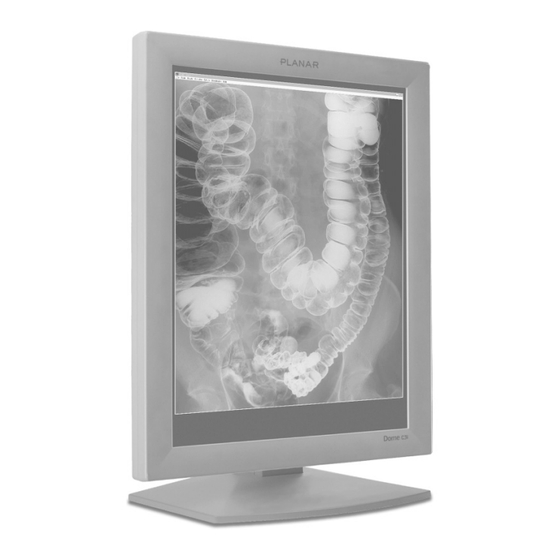
Intended use QUICK LINKS Contents The Dome C5i display is an AMLCD display designed for viewing medical X-ray images. This unit is not used near patients and is outside of 1.83 m perimeter and 2.29 m vertical. Index Regulatory Compliance... - Page 11 Troubleshooting Specifications LED Status Lights Single Desktop USB Connection Component Removal Power Management Palette Options Dome C5i Display Reasons to disconnect power • Power cord is damaged. • Liquid spills inside the display case. • Display is dropped or case is damaged.
-
Page 12: Shipping/Storing The Display
Specifications LED Status Lights Single Desktop USB Connection Component Removal Power Management Palette Options Dome C5i Display environment specifications for detailed information. Maintenance tips • Use a clean, lint-free, absorbent cotton cloth to clear off any residual glue from removal of the protective film. -
Page 13: About The Dome C5I Display
About the Dome C5i Display QUICK LINKS Contents The Dome C5i display system, 5 megapixels, consists of a thin film transistor, LCD Index panel and the DX/DX2 controller and driver. The display’s thin film transistors, in a Regulatory Compliance transmissive-type display, use an integrated cold cathode fluorescent tube (CCFT) Product Information backlight system. -
Page 14: Package Contents
QUICK LINKS Contents Index Regulatory Compliance Product Information Warranty The Dome C5i display system contains the items shown here. Speak with your sales rep GETTING STARTED if any item is missing or damaged. About the Display Package Contents Identify Components... -
Page 15: Identify The Components
USB Connection Component Removal Power Management Palette Options Dome C5i Display Back panel of the Dome C5i display Dome C5i connector plate Controls and connector ports Read the plates from left to right. Dome C5i 1 Reset button (Restores the original display configuration.) -
Page 16: Position The Display
Single Desktop USB Connection Component Removal Power Management Palette Options Dome C5i Display Height range Unfasten the stand lock at the top of the desk stand (slide it to the left) then raise or lower the panel to adjust the height. -
Page 17: Viewing Angle
APPENDIXES Troubleshooting Specifications LED Status Lights Single Desktop USB Connection Component Removal Power Management Palette Options Dome C5i Display Orientation mode Use both hands to turn the display 90 degrees clockwise to rotate the display between portrait and landscape modes. -
Page 18: Desk Stand Features
Single Desktop USB Connection Component Removal Power Management Palette Options Dome C5i Display adjust display height. Remove the stand cover to thread the Stand cover release Press the PUSH button at the bottom of the desk stand and pull the stand cover down and out to remove it. -
Page 19: Set The Dip Switch
LED Status Lights Single Desktop USB Connection Component Removal Power Management Palette Options Dome C5i Display Switch settings For single desktop mode, slide switch 3 into the ON position. The default landscape mode, set by switch 4, is unavailable for the Dome C5i display. -
Page 20: Install The Display Controller
LED Status Lights Single Desktop USB Connection Component Removal Power Management Palette Options Dome C5i Display 2 Insert the display controller into the slot, align the connector pins, and press the board down until it is firmly seated. Secure the mounting bracket. -
Page 21: Connect Video Cable And Power Supply
Turn your computer off. Leave the power cord plugged into the grounded outlet. Index Use only the video cables and the universal external 12V DC power supply shipped Regulatory Compliance with the Dome C5i display. For the Dome C5i displays, use Ault MW122RA1223F52. Product Information Secure all the connections you make. Warranty... -
Page 22: Install The Display Driver
Troubleshooting 2 Right-click the desktop. Select Properties > Settings. Specifications 3 Select the display icon. LED Status Lights 4 Select Extend my Windows desktop onto this monitor. Click Apply. Single Desktop 5 Click OK. USB Connection Component Removal Power Management... -
Page 23: Change The Display Properties
Contents You can change the display properties, such as resolution, palette options, and Index brightness, using the Dome tab after the Dome C5i display is attached to the Regulatory Compliance Windows desktop. Otherwise, use Properties > Settings tab. Product Information... - Page 24 The revision numbers USB Connection of the firmware and microcontrollers are also included. General information includes display controller type, driver version, and library version. Component Removal Power Management Palette Options Dome C5i Display...
-
Page 25: Enhancements With Dome Cxtra Software
American Association of Physicists in Medicine Task Group 18 and the DIN test INSTALLING THE DISPLAY standards. You can also monitor and maintain your Dome C5i display locally or from Set DIP Switch a remote location using any SNMP console application. -
Page 26: Troubleshooting
LED Status Lights Single Desktop USB Connection Component Removal Power Management Palette Options Dome C5i Display Possible cause Solution Computer is not powered on. Turn on computer. Power cord is not securely connected. Tighten power cord connection and turn on computer. - Page 27 Single Desktop USB Connection Component Removal Power Management Palette Options Dome C5i Display Possible cause Solution Incorrect DIP switch settings. You may need to remove the display controller to check the DIP switch settings. You can enable VGA on the display controller or use a separate VGA card.
- Page 28 C5i Display Specification QUICK LINKS Contents Category Index Screen Regulatory Compliance Product Information Warranty GETTING STARTED About the Display Package Contents Identify Components Position Display Desk Stand Features INSTALLING THE DISPLAY Set DIP Switch Interface Install Display Controller Connect Video and Power...
-
Page 29: Power Supply
Dome CXtra Software APPENDIXES Troubleshooting Specifications LED Status Lights Single Desktop USB Connection Component Removal Power Management Palette Options Dome C5i Display Characteristic Item Specification Voltage selection Auto-ranging Voltage 100 – 240V AC Current 2.0 A Frequency 50 to 60 Hz ±... - Page 30 LED Status Lights Single Desktop USB Connection Component Removal Power Management Palette Options Dome C5i Display Specification MTBF 50,000 hours with 50% duty cycle on backlight MTBF 30,000 hours to 50% brightness with backlight on continuously Specification No emission of low-level radiation operating 5°...
-
Page 31: Video Modes
The video signal connector is a standard DVI connector, driving power and data to Desk Stand Features the display. The Dome C5i display use an 8-pin DIN connector. The power input is 12V ±5% INSTALLING THE DISPLAY (100 W). Set DIP Switch... -
Page 32: Led Status Lights
LED Status Lights Single Desktop Flashing red USB Connection Component Removal Flashing yellow Power Management Palette Options Dome C5i Display Reset button (left) and LEDs on the connector plate LED A, top LED B Action/Sequence LED B Initial power-on Solid green... - Page 33 APPENDIXES Troubleshooting Specifications LED Status Lights Single Desktop USB Connection Component Removal Power Management Palette Options Dome C5i Display Description Fault Functional link – normal operation Link working, unrecognized sync information Receiving DDC information No cable detected Description Fault Functional system – normal operation...
-
Page 34: Single Desktop
Single Desktop QUICK LINKS Contents The single desktop mode converts dual Dome C5i displays into one display device Index to meet the requirements of some applications. The single desktop mode is Regulatory Compliance supported on the Dome C5i display in both portrait and landscape modes. -
Page 35: Safety Precaution
5 Set the display resolution. (See LED Status Lights Single Desktop USB Connection Component Removal Power Management Palette Options Dome C5i Display Example for Dome CX: On the Dome tab, select resolution 3072 x 2048 for the single desktop in portrait mode page page 8.) Then attach both displays to... - Page 36 Set DIP Switch Install Display Controller Connect Video and Power Install Display Driver Change Display Properties Dome CXtra Software APPENDIXES Troubleshooting Specifications LED Status Lights Single Desktop USB Connection Component Removal Power Management Palette Options Dome C5i Display page 12...
-
Page 37: Usb Connection
QUICK LINKS Contents The display desk stand contains an integrated, self-powered USB hub that allows Index you to attach USB devices (such as a keyboard or mouse) to the Dome C5i display Regulatory Compliance rather than to a computer. Product Information... -
Page 38: Display Driver And Controller Removal
Change Display Properties Dome CXtra Software APPENDIXES Troubleshooting Specifications LED Status Lights Single Desktop USB Connection Component Removal Power Management Palette Options Dome C5i Display Safety precaution Wear an antistatic wrist strap when handling the display controller to prevent electrostatic discharge. -
Page 39: Power Management
Power Management QUICK LINKS Contents You have two ways to lower energy usage when the Dome C5i display is idle: Index • Dome CXtra Backlight Saver service (preferred) Regulatory Compliance Product Information • DPMS (Display Power Management Signaling) Warranty Activate the power saver when you anticipate periods of inactivity, such as at the end of the work day. -
Page 40: Palette Options
Connect Video and Power Install Display Driver Change Display Properties Dome CXtra Software APPENDIXES Troubleshooting Specifications LED Status Lights Single Desktop USB Connection Component Removal Power Management Palette Options Dome C5i Display Non-Palette Device • Nonlinear static gray • Static gray page... - Page 41 SelectPalette and RealizePalette functions LED Status Lights select the palette into the background, and palettized devices are not Single Desktop synchronized. USB Connection Component Removal Power Management Palette Options Dome C5i Display Assignment of values on the grayscale palettes...
-
Page 42: Desktop Icons
USB Connection The dynamic gray palette accommodates gray-mapped Windows colors for Component Removal the first and last 10 palette entries. Power Management Palette Options Dome C5i Display SECONDARY DISPLAY Nonlinear Dynamic gray static gray Static gray True color ✔... - Page 43 LED Status Lights Single Desktop USB Connection Component Removal Power Management Palette Options Dome C5i Display Note Applications cannot set the nonlinear static gray palette or the static gray palette. They must read the palette from the operating system and use it when drawing directly to the framebuffer.
-
Page 44: Index
DICOM standard DIN power connector LED Status Lights DirectDraw, disabling Single Desktop USB Connection Component Removal Power Management Palette Options Dome C5i Display display connecting installing display controller installation Display Power Management Signaling display properties, changing display setup setting properties... - Page 45 Change Display Properties Dome CXtra Software APPENDIXES Troubleshooting Specifications LED Status Lights Single Desktop USB Connection Component Removal Power Management Palette Options Dome C5i Display Reset button resolution setting display retrieving display system information RightLight sensor safety precautions screen cleaning saver specifications...
-
Page 46: Overview Of Standard Warranty
Dome CX display. The Planar customer service staff will attempt to Identify Components correct any minor issues that may be causing the problem. Once Planar has determined that you have a non-functioning product, Planar will arrange for return and repair of the Position Display non-functioning product. -
Page 47: Limitation Of Implied Warranties
Accident, misuse, neglect, fire, water, lightning, or other acts of nature, unauthorized Warranty product modification, or failure to follow instructions supplied with the product. GETTING STARTED b) Repair or attempted repair by anyone not authorized by Planar. About the Display c) Any damage of the product due to shipment. Package Contents d) Removal or installation of the product. -
Page 48: Exclusion Of Damages
Exclusion of Damages QUICK LINKS Contents THE LIABILITY OF PLANAR IS LIMITED TO THE COST OF REPAIR OR REPLACEMENT OF THE PRODUCT. PLANAR SHALL NOT BE LIABLE FOR THE FOLLOWING: Index DAMAGE TO OTHER PROPERTY CAUSED BY ANY DEFECTS IN THE PRODUCT,...
Need help?
Do you have a question about the C5i and is the answer not in the manual?
Questions and answers