Advertisement
Operating Instructions and Parts Manual
SPECIFICATIONS
POWER SUPPLY REQUIREMENTS
MOTOR
HORSEPOWER
CUT IN PRESSURE
CUT OUT PRESSURE
PERFORMANCE
Model
HP
PSI
30
SWS50
1/2
40
50
30
SWS75
3/4
40
50
30
SWS100
1
40
50
© 2020, WAYNE/Scott Fetzer Company.
Please read and save these instructions. Read carefully before attempting to assemble, install,
operate or maintain the product described. Protect yourself and others by observing all safety
information. Failure to comply with instructions could result in personal injury and/or property
damage! Retain instructions for future reference.
120 or 230 V, 60 Hz
Single Phase AC Induction
1/2 HP ...................(SWS50)
3/4 HP ...................(SWS75)
1 HP ....................(SWS100)
30 PSI
50 PSI
Discharge Head (Lift Distance)
0 ft
5 ft
10 ft
15 ft
711
674
638
601
543
506
470
433
375
338
302
265
779
750
721
691
644
615
586
557
510
481
451
422
1084
1022
960
899
799
737
675
613
513
451
389
328
Intended for Indoor Use Only
Shallow Well Jet Pump Water Systems
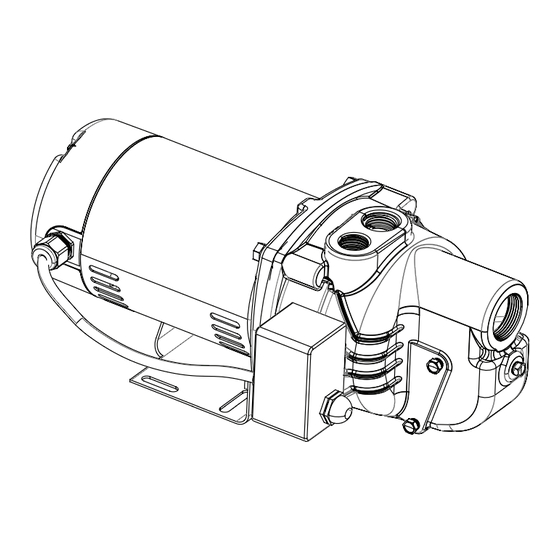
MOTOR HOUSE
SEAL PLATE
DIFFUSER
IMPELLER
SHAFT
PUMP SUCTION
PUMP DISCHARGE
20 ft
25 ft
565
529
397
361
229
193
662
633
528
499
393
364
837
775
551
490
266
204
www.waynepumps.com
CONSTRUCTION
Carbon Steel
Cast Iron
Thermoplastic
Thermoplastic
Stainless Steel
1-1/4 in. NPT
1 in. NPT
640002W-001 F 08/20
SWS
Advertisement
Table of Contents

Subscribe to Our Youtube Channel
Related Manuals for Wayne SWS Series


Summary of Contents for Wayne SWS Series
- Page 1 1 in. NPT PERFORMANCE Discharge Head (Lift Distance) Model 0 ft 5 ft 10 ft 15 ft 20 ft 25 ft SWS50 SWS75 1084 1022 SWS100 Intended for Indoor Use Only 640002W-001 F 08/20 www.waynepumps.com © 2020, WAYNE/Scott Fetzer Company.
-
Page 2: General Safety Information
Operating Instructions and Parts Manual DESCRIPTION GENERAL SAFETY INFORMATION Shallow well jet pumps are single stage residential water pumps CALIFORNIA PROPOSITION 65 designed for pumping potable water in applications where the water is located less than 25 feet vertically from the pump. A pressure switch is a standard feature. -
Page 3: Pre-Installation
Operating Instructions and Parts Manual GENERAL SAFETY INFORMATION (CONT'D) Do NOT touch an operating motor. Modern motors are designed to operate at high temperatures. Disconnect power and release all pressure from the system before attempting to install, service, relocate or perform any Ne touchez PAS un monteur en fonctionnement. -
Page 4: Installation
Operating Instructions and Parts Manual PRE-INSTALLATION (CONT'D) Flexible pipe is prohibited on suction pipe (inlet pipe). TANKS - CONVENTIONAL STORAGE MISE EN GARDE The function of the tank is to store a quantity of water under Un tuyau flexible est interdit sur le tuyau pressure. - Page 5 Operating Instructions and Parts Manual DUG WELL, CISTERN, LAKE AND SPRING INSTALLATION (FIGURE 12 ON PAGE 11) The foot valve MUST be at least 18” from the 1. Install a foot valve on inlet pipe and lower into water. bottom of the well or sand or sediment WILL be drawn into the system. MISE EN GARDE Le clapet de pied DOIT au moins être The foot valve MUST be at least 18”...
-
Page 6: Operation
Operating Instructions and Parts Manual ELECTRICAL the system before attempting to install, service, relocate or perform any maintenance. Risk of electrical shock. This pump is designed for indoor installation unless housed and protected from the elements. Débrancher de la source d’alimentation puis dissiper toute la pression du système avant d’essayer d’installer, de Risque de choc électrique! Cette pompe est réparer, de déplacer ou de procéder à... -
Page 7: Maintenance
Operating Instructions and Parts Manual MAINTENANCE OUTLET AIR VOLUME Disconnect power and release all pressure from AIR VOLUME the system before attempting to install, service, relocate or perform any HOSE COUPLING maintenance. Lock the power disconnect in the open (OFF) position. Tag out the power disconnect to prevent unexpected application of power. - Page 8 Operating Instructions and Parts Manual KITS SECTION (CONT'D) SEAL PLATE IMPELLER 8. Remove the seal plate. ROTATING SHAFT 9. Pry the rotating shaft seal member (including stainless collar SEAL MEMBER and rubber seal) from the impeller (Figure 9). RUBBER SEAT RING 10.
- Page 9 Please provide following information: Address any correspondence to: - Model number WAYNE Pumps 101 Production Drive - Serial number (if any) Harrison, OH 45030 U.S.A. - Part description and number as shown in parts list 1, 2, 3 Ref.
-
Page 10: Troubleshooting Chart
Operating Instructions and Parts Manual TROUBLESHOOTING CHART Symptoms Possible Cause(s) Suggested Remedies Pump will not 1. Power off 1. Turn power on or call power company start or run 2. Blown fuse or tripped breaker 2. Replace fuse or reset circuit breaker 3. - Page 11 Operating Instructions and Parts Manual...
- Page 12 LIMITED WARRANTY For three years for SWS50, SWS75 and SWS100 models from the date of purchase, from an authorized dealer, WAYNE Pumps will repair or replace, at its option for the original purchaser, any part or parts of its Well Pumps or Water Pumps (“Product”) found upon examination by WAYNE Pumps to be defective in materials or workmanship.
Need help?
Do you have a question about the SWS Series and is the answer not in the manual?
Questions and answers