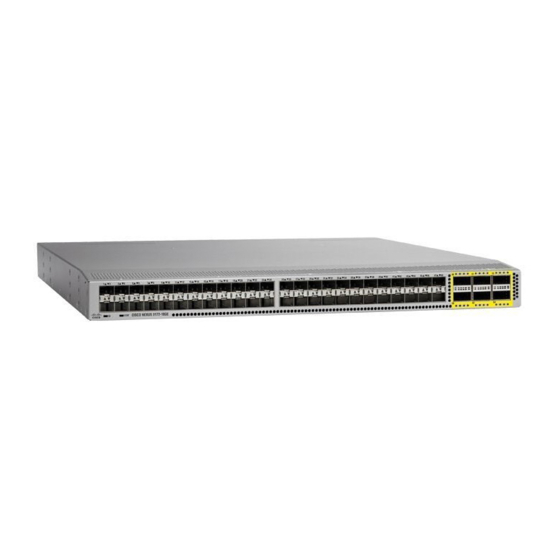
Cisco Nexus 3000 Series Manual
Hide thumbs
Also See for Nexus 3000 Series:
- Installation manual ,
- Command reference manual (356 pages) ,
- Configuration manual (338 pages)
Table of Contents
Advertisement
Quick Links
Installing the Chassis
•
•
•
•
•
•
Safety
Before you install, operate, or service the switch, see the Regulatory, Compliance, and Safety Information for
the Cisco Nexus 3000 and 9000 Series for important Safety Information.
Warning
Warning
Safety, on page 1
Preparing to Install the Chassis, on page 4
Unpacking and Inspecting the Chassis, on page 6
Installing the Chassis in a Four-Post Rack, on page 7
Grounding the Chassis, on page 12
Starting the Switch, on page 14
Statement 1071 Warning Definition
IMPORTANT SAFETY INSTRUCTIONS
Before you work on any equipment, be aware of the hazards involved with electrical circuitry and be familiar
with standard practices for preventing accidents. Read the installation instructions before using, installing, or
connecting the system to the power source. Use the statement number provided at the end of each warning
statement to locate its translation in the translated safety warnings for this device.
SAVE THESE INSTRUCTIONS
Statement 1089 Instructed and Skilled Person Definitions
An instructed person is someone who has been instructed and trained by a skilled person and takes the necessary
precautions when working with equipment.
A skilled person or qualified personnel is someone who has training or experience in the equipment technology
and understands potential hazards when working with equipment.
Installing the Chassis
1
Advertisement
Table of Contents

Related Manuals for Cisco Nexus 3000 Series


Summary of Contents for Cisco Nexus 3000 Series
- Page 1 Starting the Switch, on page 14 Safety Before you install, operate, or service the switch, see the Regulatory, Compliance, and Safety Information for the Cisco Nexus 3000 and 9000 Series for important Safety Information. Warning Statement 1071 Warning Definition IMPORTANT SAFETY INSTRUCTIONS Before you work on any equipment, be aware of the hazards involved with electrical circuitry and be familiar with standard practices for preventing accidents.
- Page 2 Note Statement 407 Japanese Safety Instruction You are strongly advised to read the safety instruction before using the product. https://www.cisco.com/web/JP/techdoc/pldoc/pldoc.html When installing the product, use the provided or designated connection cables/power cables/AC adapters. Warning Statement 1017 Restricted Area This unit is intended for installation in restricted access areas.
- Page 3 Installing the Chassis Safety Warning Statement 1028 More Than One Power Supply This unit might have more than one power supply connection. To reduce risk of electric shock, remove all connections to de-energize the unit. Warning Statement 1003 DC Power Disconnection To reduce risk of electric shock or personal injury, disconnect DC power before removing or replacing components or performing upgrades.
-
Page 4: Preparing To Install The Chassis
Installing the Chassis Preparing to Install the Chassis Warning Statement 1252 Equipment Grounding This equipment must be grounded. To reduce the risk of electric shock, the power cord, plug, or combination must be connected to a properly grounded electrode, outlet, or terminal. Warning Statement 1076 Clearance Around the Ventilation Openings To prevent airflow restriction, allow clearance around the ventilation openings to be at least 30cm. - Page 5 Caution Avoid UPS types that use ferroresonant technology. These UPS types can become unstable with systems such as the Cisco Nexus switches. These switches can have substantial current draw fluctuations because of fluctuating data traffic patterns. Ensure that circuits are sized according to local and national codes. For North America, the power supply requires a 15-A or 20-A circuit.
-
Page 6: Unpacking And Inspecting The Chassis
Installing the Chassis Unpacking and Inspecting the Chassis • Eight customer-supplied 12-24 or 10-32 screws (required for attaching slider rails and mounting bracket to the mounting rails) • Number 1 and number 2 Phillips screwdrivers with torque capability • 3/16-inch flat-blade screwdriver •... -
Page 7: Installing The Chassis In A Four-Post Rack
• Port-side exhaust airflow direction indicated with blue coloring Installing the Chassis in a Four-Post Rack This section describes the installation of the Cisco Nexus 9408 platform switch, into a four-post rack, using the N9K-C9400-RMK rack-mount kit. Before moving or lifting the chassis, follow these guidelines: •... - Page 8 Installing the Chassis Installing the Chassis in a Four-Post Rack Warning Statement 164 Lifting Requirement people are required to lift the heavy parts of the product. To prevent injury, keep your back straight and lift with your legs, not your back. Warning Statement 1006 Chassis Warning for Rack-Mounting and Servicing To prevent bodily injury when mounting or servicing this unit in a rack, you must take special precautions to...
- Page 9 Installing the Chassis Installing the Chassis in a Four-Post Rack Figure 1: Aligning and Attaching Front-Mount Brackets to the Chassis Front rack-mount bracket M4 x 6-mm screws b) Use M4 x 6 mm screws to attach the bracket to the chassis and tighten each screw to 12 in-lb (1.36 N·m) of torque. c) Repeat Steps 1a and 1b to attach the other front-mount bracket to the other side of the chassis.
- Page 10 Installing the Chassis Installing the Chassis in a Four-Post Rack Figure 2: Aligning the Bottom-Support Rails Bottom-support rail (2) Step 3 Attach the bottom-support rails on the rack as follows: a) Position an expanding set of bottom-support brackets on the rack with each end touching a vertical mounting rail on the front and rear of the rack as shown in the following figure.
- Page 11 Installing the Chassis Installing the Chassis in a Four-Post Rack Figure 3: Positioning the Bottom-Support Rails Screws holding the bottom-support bracket to the rack The bottom-support brackets (2) b) Holding the bottom-support rail level, attach the rail to the front and rear vertical mounting rails using four customer-supplied screws that are appropriate for the rack (use two screws for each vertical mounting rail), and tighten each screw to the appropriate torque setting for that screw.
-
Page 12: Grounding The Chassis
Installing the Chassis Grounding the Chassis When you have fully pushed the chassis all the way onto the bottom-support rails, the chassis stops when the front-mount brackets touch the front vertical mounting rack. Figure 4: Sliding the Chassis onto the Bottom-Support Rails Rack-mount screw b) Use screws that are appropriate for the rack to attach the front-mount brackets to the rack. - Page 13 Installing the Chassis Grounding the Chassis You can alternatively ground the chassis (this is required if the rack is not grounded) by attaching a customer-supplied grounding cable to the chassis grounding pad and the facility ground. Note The location of the grounding pad on each switch can be found in the Overview section.
-
Page 14: Starting The Switch
Installing the Chassis Starting the Switch information) that now has a connection to the data center earth ground, you can ground the chassis by installing it into the rack. Otherwise, you must connect the chassis grounding pad directly to the data center ground. Step 1 Use a wire-stripping tool to remove approximately 0.75 inches (19 mm) of the covering from the end of the grounding wire. - Page 15 Installing the Chassis Starting the Switch Before you begin • Verify that the switch is fully installed and secured to a rack. • Verify that the switch is adequately grounded to the facility earth ground or to a grounded rack. •...
- Page 16 Installing the Chassis Starting the Switch Installing the Chassis...
Need help?
Do you have a question about the Nexus 3000 Series and is the answer not in the manual?
Questions and answers