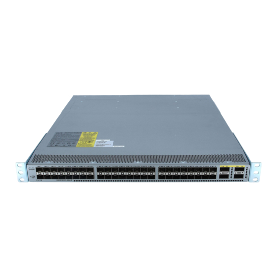
Cisco Nexus 3000 Quick Start Manual
Hide thumbs
Also See for Nexus 3000:
- Installation manual ,
- Command reference manual (356 pages) ,
- Configuration manual (338 pages)
Table of Contents
Advertisement
Quick Links
Installing the Chassis
•
•
•
•
•
•
•
•
•
Safety
Before you install, operate, or service the switch, see the Regulatory, Compliance, and Safety Information for
the Cisco Nexus 3000 and 9000 Series for important Safety Information.
Warning
Warning
Safety, on page 1
Installation Options with Rack-Mount Kits, on page 4
Airflow Considerations, on page 5
Installation Guidelines, on page 5
Unpacking and Inspecting the Switch, on page 6
Installing the Airflow Sleeve (N9K-AIRFLOW-SLV), on page 10
Grounding the Chassis, on page 11
Starting the Switch, on page 13
Statement 1071 Warning Definition
IMPORTANT SAFETY INSTRUCTIONS
Before you work on any equipment, be aware of the hazards involved with electrical circuitry and be familiar
with standard practices for preventing accidents. Read the installation instructions before using, installing, or
connecting the system to the power source. Use the statement number provided at the end of each warning
statement to locate its translation in the translated safety warnings for this device.
SAVE THESE INSTRUCTIONS
Statement 1089 Instructed and Skilled Person Definitions
An instructed person is someone who has been instructed and trained by a skilled person and takes the necessary
precautions when working with equipment.
A skilled person or qualified personnel is someone who has training or experience in the equipment technology
and understands potential hazards when working with equipment.
Installing the Chassis
1
Advertisement
Table of Contents

Related Manuals for Cisco Nexus 3000


Summary of Contents for Cisco Nexus 3000
-
Page 1: Table Of Contents
Starting the Switch, on page 13 Safety Before you install, operate, or service the switch, see the Regulatory, Compliance, and Safety Information for the Cisco Nexus 3000 and 9000 Series for important Safety Information. Warning Statement 1071 Warning Definition IMPORTANT SAFETY INSTRUCTIONS Before you work on any equipment, be aware of the hazards involved with electrical circuitry and be familiar with standard practices for preventing accidents. - Page 2 Material Safety Law prohibits the use of UL-certified cables (that have the "UL" or "CSA" shown on the cord), not regulated with the subject law by showing "PSE" on the cord, for any other electrical devices than products designated by Cisco. Note Statement 407 Japanese Safety Instruction You are strongly advised to read the safety instruction before using the product.
- Page 3 Installing the Chassis Safety Warning Statement 1030 Equipment Installation Only trained and qualified personnel should be allowed to install, replace, or service this equipment. Warning Statement 1091 Installation by an Instructed Person Only an instructed person or skilled person should be allowed to install, replace, or service this equipment. See statement 1089 for the definition of an instructed or skilled person.
-
Page 4: Installation Options With Rack-Mount Kits
You can install the switch using the following rack-mount options: • Rack-mount kit (NXK-ACC-KIT-1RU) which you can order from Cisco. This option offers you easy installation, greater stability, increased weight capacity, added accessibility, and improved removability with front and rear removal. -
Page 5: Airflow Considerations
Installing the Chassis Airflow Considerations Note You are responsible for verifying that your rack and rack-mount hardware comply with the guidelines that are described in this doc. Airflow Considerations The switch comes with fan and power supply modules that have either port-side intake or port-side exhaust airflow for cooling the switch. -
Page 6: Unpacking And Inspecting The Switch
Installing the Chassis Unpacking and Inspecting the Switch Warning Statement 1005 Circuit Breaker This product relies on the building's installation for short-circuit (overcurrent) protection. Ensure that the protective devices is rated not greater than 20A (North America), 16A (Europe), and 13A (UK). Note For DC input application, please refer to the statement below: Warning... -
Page 7: Installing The Switch Using The Nxk-Acc-Kit-1Ru Rack-Mount Kit
Installing the Chassis Installing the Switch Using the NXK-ACC-KIT-1RU Rack-Mount Kit • Effect of damage on the installation Installing the Switch Using the NXK-ACC-KIT-1RU Rack-Mount To install the switch, you must attach front and rear mounting brackets to the switch, install slider rails on the rear of the rack, slide the switch onto the slider rails, and secure the switch to the front of the rack. - Page 8 Installing the Chassis Installing the Switch Using the NXK-ACC-KIT-1RU Rack-Mount Kit c) Secure the front-mount bracket and the back-mount bracket to the chassis using four M4 screws and tighten each screw to 12 in-lb (1.36 N·m) of torque. d) Repeat Step 1 for the other front rack-mount bracket and the other back-mount bracket on the other side of the switch and be sure to position that bracket the same distance from the front of the switch.
- Page 9 Installing the Chassis Installing the Switch Using the NXK-ACC-KIT-1RU Rack-Mount Kit c) Repeat Step 3 to attach the other slider rail to the other side of the rack. To make sure that the slider rails are at the same level, you should use a level tool, tape measure, or carefully count the screw holes in the vertical mounting rails.
-
Page 10: Installing The Airflow Sleeve (N9K-Airflow-Slv)
Installing the Chassis Installing the Airflow Sleeve (N9K-AIRFLOW-SLV) d) Tighten the 10-32 screws to 20 in-lb (2.26 N·m) or tighten the 12-24 screws to 30 in-lb (3.39 N·m). Step 5 If you attached a grounding wire to the chassis grounding pad, connect the other end of the wire to the facility ground. Installing the Airflow Sleeve (N9K-AIRFLOW-SLV) The airflow sleeve (N9K-AIRFLOW-SLV) is installed to allow proper airflow, so that the switch is properly cooled. -
Page 11: Grounding The Chassis
Installing the Chassis Grounding the Chassis Chassis Minimum Rack Depth Maximum Rack Depth N9K-C93180YC-FX3S 672.49 mm 784.25 mm N9K-C93600CD-GX 824.80 mm 916.60 mm Note You supply the screws to mount the airflow sleeve. Before you begin • Verify that your shipment is complete. •... - Page 12 Installing the Chassis Grounding the Chassis Note An electrical conducting path shall exist between the product chassis and the metal surface of the enclosure or rack in which it is mounted or to a grounding conductor. Electrical continuity shall be provided by using thread-forming type mounting screws that remove any paint or non-conductive coatings and establish a metal-to-metal contact.
-
Page 13: Starting The Switch
Installing the Chassis Starting the Switch Grounding cable, with 0.75 in. (19 mm) of insulation that is stripped from one end, which is inserted into the grounding lug and crimped in place Step 3 Secure the grounding lug to the chassis grounding pad with two M4 screws, see the previous figure. Tighten the screws to 11 to 15 in-lb (1.24 to 1.69 N·m) of torque. - Page 14 A setup utility automatically launches the first time that you access the switch and guides you through the basic configuration. For instructions on how to configure the switch and check module connectivity, see the appropriate Cisco Nexus 9000 Series configuration guide.
Need help?
Do you have a question about the Nexus 3000 and is the answer not in the manual?
Questions and answers