
Subscribe to Our Youtube Channel
Related Manuals for RKI Instruments 65-2443-100


Summary of Contents for RKI Instruments 65-2443-100
- Page 1 65-2443-XX PPM Hydrogen Transmitter Operator’s Manual Part Number: 71-0542 Revision: 0 Released: 5/8/23 RKI Instruments, Inc. www.rkiinstruments.com...
- Page 2 WARNING Read and understand this instruction manual before operating instrument. Improper use of the gas monitor could result in bodily harm or death. Periodic calibration and maintenance of the gas monitor is essential for proper operation and correct readings. Please calibrate and maintain this instrument regularly! Frequency of calibration depends upon the type of use you have and the sensor types.
- Page 3 RKI Instruments, Inc. Any parts found defective within that period will be repaired or replaced, at our option, free of charge. Parts must be returned to RKI Instruments, Inc. for repair or replacement. This warranty does not apply to those items which by their nature are subject to deterioration or consumption in normal service, and which must be cleaned, repaired or replaced on a routine basis.
-
Page 4: Table Of Contents
Table of Contents Overview ............5 Specifications . -
Page 5: Overview
Table 1 lists specifications for the ppm hydrogen transmitter. Table 1: Specifications Target Gas Hydrogen (H • 65-2443-100: 0 - 100 ppm • 65-2443-500: 0 - 500 ppm Detection Range • 65-2443-1000: 0 - 1,000 ppm • 65-2443-2000: 0 - 2,000 ppm... -
Page 6: Description
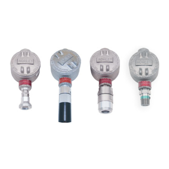
Description This section describes the ppm hydrogen transmitter’s components. It is a 4 to 20 mA type detector head. It consists of the ppm hydrogen detector, amplifier, and junction box. Amplifier S PA N J-Box Reducing Bushing, Hydrogen Detector 3/4 NPT t o 1/2 NPT Figure 1: Component Location 6 •... -
Page 7: Ppm Hydrogen Detector
PPM Hydrogen Detector The ppm hydrogen detector is a MOS type (metal oxide semiconductor) detector packaged in a 1/ 2 NPT nipple with a sintered metal flame arrestor on one end allowing ambient air to diffuse into the detector. The flame arrestor also contains any sparks which may occur within the detector. The 1/2 NPT mounting threads at the top of the detector allow you to mount it into the bottom conduit hub of the junction box. -
Page 8: Junction Box
Detector Terminal Strip The detector terminal strip is a three position plug-in style terminal strip located below the controller terminal strip. Use the detector terminal strip to connect the detector to the amplifier. NOTE: The detector is factory-wired to the detector terminal strip. See page 10 for all wiring procedures related to the transmitter. -
Page 9: Installation
Installation This section describes procedures to mount the ppm hydrogen transmitter in the monitoring environment and wire the transmitter to a controller. Mounting the PPM Hydrogen Transmitter 2.70 3/4 NPT Female 3.65 7.5 m ax Rubber Spacers, J Box 3/4 x 1/2 Reducing Bushing Hydrogen Detector... -
Page 10: Wiring The Ppm Hydrogen Transmitter
Wiring the PPM Hydrogen Transmitter WARNING: Always verify that the power to the controller is off before you make wiring connections. 1. Turn off power to the controller. 2. Place the controller’s power switch in the OFF position. 3. Remove the junction box cover. 4. - Page 11 11. Connect the wires to the applicable detector/transmitter terminal strip at the controller as shown in Figure 4. + 24 V DC 4 - 20 m A In (S ) - (DC Ground) Controller Cable S hield Black Detector W ires SPAN W hite Figure 4: Wiring the PPM Hydrogen Transmitter to a Controller...
-
Page 12: Startup
Start Up This section describes procedures to start up the ppm hydrogen transmitter and place the transmitter into normal operation. Introducing Incoming Power 1. Complete the installation procedures described earlier in this manual. 2. Verify that the power wiring to the controller is correct and secure. Refer to the controller operator’s manual. -
Page 13: Maintenance
Maintenance This section describes maintenance procedures. It includes preventive maintenance, troubleshooting, and component replacement procedures. Preventive Maintenance This section describes a preventive maintenance schedule to ensure the optimum performance of the ppm hydrogen transmitter. It includes daily and quarterly procedures. Daily Verify a display reading of 0 ppm at the controller. -
Page 14: Replacing Components Of The Ppm Hydrogen Transmitter
Table 2: Troubleshooting the ppm Hydrogen Transmitter (Continued) Condition Symptom(s) Probable Causes Recommended Action • Unable to accurately • The calibration 1. Verify that the calibration Slow or No cylinder contains an adequate set the span or cylinder is low, Response/ supply of gas. - Page 15 Table 3: Reconnecting the PPM Detector to the Amplifier Detector Terminal Detector Lead Strip White Black 9. Re-install the detector terminal strip into its socket. NOTE: When a transmitter is first powered up with a new detector, its output may be high enough to cause an alarm or low enough to indicate a failure for a brief period before stabilizing within a few minutes.
- Page 16 7. Install the detector and controller terminal strips into their sockets on the new amplifier as shown in Figure 4 on page 11 of this manual. If controller leads or detector leads were removed during this procedure, refer to Tables 4 and 5 below. Table 4: Reconnecting the PPM Hydrogen Amplifier to the Controller Amplifier’s Controller’s...
-
Page 17: Calibration Frequency
Although there is no particular calibration frequency that is correct for all ppm hydrogen transmitter applications, a calibration frequency of every 6 to 12 months is adequate for most applications. Unless experience in a particular application dictates otherwise, RKI Instruments, Inc. recommends a calibration frequency of every 6 months. -
Page 18: Preparing For Calibration
• calibration gas cylinder with a full-scale concentration • calibration gas cylinder with a half-scale concentration Calibration Gas Detection Range Concentrations • 50 ppm H 0 - 100 ppm H • 100 ppm H • 250 ppm H 0 - 500 ppm H •... -
Page 19: Setting The Span Reading
Setting the Span Reading The configuration of the JP1 and JP2 jumpers may need to be adjusted during calibration. Valid configurations are: Detection Range Valid Jumper Configurations • JP1 and JP2 both installed on one pin 0 - 100 ppm H •... -
Page 20: Setting The Linearization
Setting the Linearization 1. Screw the regulator into the half-scale calibration cylinder. 2. Turn the regulator knob counterclockwise to open the regulator. 3. Allow the calibration gas to flow for 2 minutes. 4. Verify a reading of 300 mV (±2 mV) on the voltmeter. If necessary, use the linear pot on the amplifier to adjust the reading. -
Page 21: Parts List
24” humidifier tube w/ 3/16” tubing on ends, for calibration kit 57-1070-01 Amplifier (specify target gas and detection range) 61-0160RK PPM hydrogen detector, for all ranges 65-2443-100 0 - 100 ppm hydrogen transmitter (includes detector and amplifier) 65-2443-500 0 - 500 ppm hydrogen transmitter (includes detector and amplifier) 65-2443-1000... - Page 22 Table 6: Parts List Part Number Description 81-1117RK Calibration cup 81-F072RK Calibration kit, includes regulator, humidifier tube, calibration cup, 103 liter 1,000 ppm hydrogen calibration cylinder, and 103 liter 2,000 ppm hydrogen calibration cylinder 81-F072RK-LV Calibration kit, includes regulator, humidifier tube, calibration cup, 34 liter 1,000 ppm hydrogen steel calibration cylinder, and 34 liter 2,000 ppm hydrogen steel calibration cylin- 81-F073RK-LV Calibration kit, includes regulator, humidifier tube, calibration cup, 34 liter 500 ppm hydro-...
Need help?
Do you have a question about the 65-2443-100 and is the answer not in the manual?
Questions and answers