Advertisement
Quick Links
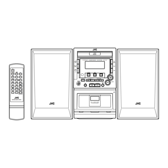
SERVICE MANUAL
COMPACT COMPONENT SYSTEM
STANDBY/ON
TUNER
CD/RANDOM
/BAND
TAPE
REC
PROGRAM
REMAIN
SLEEP
PRE UP
REPEAT
INTRO
TIMER
/PRE DOWN
DISPLAY
+
MODE
PRE EQ/HBS
VOLUME
MUTING
BEAT CUT
-
RM-SFSM3J REMOTE CONTROL
Contents
Safety precautions
on the safety
FS-M3
C O M P A C T
C O M P O N E N T
S Y S T E M
STANDBY
/ON
DISPLAY
MODE
TIMER
ON/OFF
SET
RANDOM
BAND
CD
TUNER
PROGRAM
PRESET
SEARCH/TUNING
REPEAT
PHONES
REC
STOP/CLEAR
PLAY/PAUSE
F U L L L O G I C D E C K
CD SYNCHRO RECORDING
1-2
1-3
1-4
1-5
1-6
1-15
COPYRIGHT
2002 VICTOR COMPANY OF JAPAN, LTD.
J ----------------------------- U.S.A.
C -------------------------- Canada
F S - M 3
OPEN
/CLOSE
REMAIN
INTRO
TAPE
VOLUME
PRE EQ
/HBS
EJECT
Flow of functional operation
until TOC read
Maintenance of laser pickup
Trouble shooting
FS-M3
Area suffix
1-18
1-19
1-19
1-20
1-21
1-29
No.21067
Feb. 2002
Advertisement

Subscribe to Our Youtube Channel
Related Manuals for JVC FS-M3


Summary of Contents for JVC FS-M3
-
Page 1: Table Of Contents
FS-M3 SERVICE MANUAL COMPACT COMPONENT SYSTEM FS-M3 Area suffix J ----------------------------- U.S.A. C -------------------------- Canada C O M P A C T C O M P O N E N T S Y S T E M F S - M 3... - Page 2 FS-M3 1. This design of this product contains special hardware and many circuits and components specially for safety purposes. For continued protection, no changes should be made to the original design unless authorized in writing by the manufacturer. Replacement parts must be identical to those used in the original circuits. Services should be performed by qualified personnel only.
-
Page 3: Preventing Static Electricity
FS-M3 Preventing static electricity 1. Grounding to prevent damage by static electricity Electrostatic discharge (ESD), which occurs when static electricity stored in the body, fabric, etc. is discharged, can destroy the laser diode in the traverse unit (optical pickup). Take care to prevent this when performing repairs. -
Page 4: Important For Laser Products
FS-M3 Important for laser products 5.CAUTION : If safety switches malfunction, the laser is able 1.CLASS 1 LASER PRODUCT to function. 2.DANGER : Invisible laser radiation when open and inter 6.CAUTION : Use of controls, adjustments or performance of lock failed or defeated. Avoid direct exposure to beam. -
Page 5: Importance Administering Point
FS-M3 Importance administering point on the safety F903 Caution: For continued protection against risk of fire, replace only with same type 1.6A/250V for F901,3.15A/250V for F902,1.6A/250V for F903. This symbolspecifies type of fast operating fuse. Precaution: Pour eviter risques de feux, remplacez le fusible de surete de F901 comme le meme type que 1.6A/250V,F902 comme le meme type que... -
Page 6: Disassembly Method
FS-M3 Disassembly method Fuse(F902) <Main body section> 3.15A 250V Power board Fuse(F903) Replacement of the fuses and power amplifier IC 1.6A 250V Replacing the fuses (See Fig. 1.) Remove the left side panel according to its disassembly method (see Figs. 5 and 6). - Page 7 FS-M3 Removing the right side panel (See Figs. 3 and 4.) From the right side of the main body, remove the Right side three screws B and three screws C retaining the panel right side panel. Slide the right side panel toward the rear (in the...
- Page 8 FS-M3 Removing the top cover (To be loosened) (See Figs. 7 and 8.) Top cover Remove the left and right side panels. From the back side of the main body, loosen the two screws D retaining the top cover. Rear panel Lift the rear part of the top cover to remove it.
- Page 9 FS-M3 Removing the CD mechanism assembly (See Figs. 12 to 14.) CN701 CN601 CN603 CD & MCU board CN602 Remove the left and right side panels. Remove the top cover. Remove the front panel assembly. Disconnect the wires from the four connectors CN601, CN602, CN603 and CN701 on the CD &...
- Page 10 FS-M3 Removing the power board Stud Main board Power transformer CN901 Stud (See Figs. 15 and 16.) Remove the left and right side panels. Disconnect the wire from the connector CN901 on the power board. Remove the two screws L retaining the chassis .
- Page 11 FS-M3 <Front panel assembly section> Key switch board Front panel assembly Remove the left and right side panels. Remove the top cover. Remove the front panel assembly. Removing the key switch board (See Fig. 19.) Remove the ten screws P retaining the key switch board.
- Page 12 FS-M3 <CD mechanism section> Remove the left and right side panels. CD & MCU board Stud Remove the top cover. CN702 Remove the front panel assembly. Remove the CD mechanism assembly. Removing the CD & MCU board (See Figs. 23 and 24.)
- Page 13 FS-M3 Removing the tray motor CD mechanism assembly (See Figs. 26 to 29.) Clamper assembly Claw p Remove the CD & MCU board. On the top of the CD mechanism assembly, open up the claws p and q at the left and right of the...
- Page 14 FS-M3 Clamper assembly Front panel assembly Replacing the CD pickup unit Claw p (See Figs. 30 to 33.) [Note] Use the following procedure to replace only the CD pickup unit. Remove the left and right side panels (see Figs. 3 to 6).
-
Page 15: Adjustment Method
FS-M3 Adjustment method Measuring instructions required for Measuring instruments adjustment Radio section FM 1kHz, 22.5kHz deviation 1. AM signal generator FM STEREO : 1kHz, 67.5kHz deviation 2. FM signal generator pilot signal 7.5kHz 3. Inter mediate frequency sweep generator AM : 1kHz, 30% modulation 4. - Page 16 FS-M3 Cassette amplifier section Item Measuring condition Check and adjustment procedure Standard value Adjusting part Head azimuth Test tape: Play back the test tape VT703 (10kHz). Output level: Head azimuth adjustment VT703 (10kHz) Adjust the head azimuth adjusting screw so that the...
- Page 17 FS-M3 Location of adjusting parts Cassette mechanism section (Caution) For adjusting any head, be sure to use a screw driver degaussed. Adjustment Head CASSETTE MOTOR Tape Speed Adj. Azimuth adjustment screw Fig.1 Head output signal Fig.2 Main board P101 (AM VT)
- Page 18 FS-M3 Flow of functional operation until TOC read Confirm that the voltage at the pin5 of CN703 is Slider turns REST Power ON "H"/"L"/"H" SW ON. Check that the voltage at the pin10(LD) of Laser ON CN704 is +1.35V. Caution...
-
Page 19: Replacement Of Laser Pickup
FS-M3 Maintenance of laser pickup Replacement of laser pickup (1) Cleaning the pick up lens Before you replace the pick up, please try to Turn off the power switch and,disconnect the clean the lens with a alcohol soaked cotton power cord from the AC OUTLET. - Page 20 FS-M3 Trouble shooting Circuit Symptom Cause Remedy General No sound Speakers are not connected. Check the speaker connection. Wrong function is selected. Set switch to the proper position. Defective volume control Set the volume control to a proper sound level.
-
Page 21: Description Of Major Ics
FS-M3 Description of major ICs 87EP26F-1J15 (IC601) : MCU 1. Terminal layout (Top view) 2.Pin function Symbol Function Symbol Function GND (0V) B-PHOTO OUTPUT Reel pulse input of deck B. Have pulse input means XOUT Resonator connecting pins for high clock(4-8MHz). - Page 22 FS-M3 TC9462F (IC701) : Digital servo single chip processor 1. Terminal layout 80 ~ 51 1 ~ 30 2. Pin function Pin No. Symbol Function Pin No. Symbol Function TEST0 Te s t m o d e t e r m i n a l . N o r m a l l y, k e e p a t o p e n VDD2 D i g i t a l p o w e r s u p p l y v o l t a g e t e r m i n a l .
- Page 23 FS-M3 Pin No. Symbol Function Pin No. Symbol Function RFGC R F a m p l i t u d e a d j u s t m e n t c o n t r o l s i g n a l o u t p u t TESIN Te s t i n p u t t e r m i n a l .
- Page 24 FS-M3 AN7312 (IC202) : Dual recording/Playback pre-amplifier circuit with ALC 1. Terminal layout 2. Block diagram Amp. Ripple Filter Amp. 3. Pin function Symbol Function Pin No. ALC time constant ALC time constant by resistance and capacitor ALC input Ch.1 Right channel ALC input Output Ch.1...
- Page 25 FS-M3 TA2109F (IC704) : RF Amplifier 1.Terminal Layout 2.Block Diagram SBAD 2VRO AGCI RFGC 3 STATE RFGO RFIS RFRP RFRP RFIS 2VRO PEAK BOTTOM SBAD RFGO RFGC AGCI 3.Pin Function Pin No. Symbol Function Power supply input terminal Main beam I-V amplifier input terminal...
- Page 26 FS-M3 TA2104BN (IC101) : 1chip AM/FM, MPX tuner system 1. Terminal layout 2. Pin function No. Symbol Function Symbol I/O Function RFGND FMRF OUT FMRF IN RF VCC RFGND Ground terminal for RF LPF2 FM/AM switch AMRF IN FMRF IN...
- Page 27 FS-M3 TC9422F (IC301) : System electronic volume 1.Terminal Layout 2.Block Diagram INPUT SELECTOR INPUT SELECTOR 100k 100k R-IN1 L-IN1 R-IN1 L-IN1 L-IN2 R-IN2 R-IN2 L-IN2 R-IN3 L-IN3 L-IN3 R-IN3 R-IN4 L-IN4 GAIN CONTROL GAIN CONTROL 0,6,12,18dB 0,6,12,18dB R SW-OUT L SW-OUT...
- Page 28 FS-M3 TA2092N (IC703) : Power driver IC 1.Terminal Layout & Block Diagram 2.Pin Function Pin No. Symbol Function Power GND PW GND1 PW GND1 PW GND4 Inverted output for CH1 OUT(-)1 OUT(-)1 OUT(-)4 Supply terminal of output stage for CH1...
-
Page 29: Wiring Connections
FS-M3 Wiring connections 1-29... - Page 30 FS-M3 VICTOR COMPANY OF JAPAN, LIMITED AUDIO & COMMUNICATION BUSINESS DIVISION PERSONAL & MOBILE NETWORK BUSINESS UNIT. 10-1,1Chome,Ohwatari-machi,maebashi-city,371-8543,Japan No.21067 200202(SV)
- Page 31 FS-M3 PARTS LIST [ FS-M3 ] * All printed circuit boards and its assemblies are not available as service parts. Area suffix J ----------------------------- U.S.A. C -------------------------- Canada - Contents - 3- 3 Exploded view of general assembly and parts list (Block No.M1) 3- 5 Electrical parts list (Block No.01~04)
- Page 32 FS-M3 < M E M O >...
- Page 33 FS-M3 Exploded view of general assembly and parts list Block No. Back light board CD&MCU board Key switch board H.P.jack board Main board Power board...
- Page 34 FS-M3 FS-M3 Parts list (General assembly) Parts list (General assembly) Block No. M1MM Block No. M1MM Item Parts number Parts name Q'ty Description Area Item Parts number Parts name Q'ty Description Area OW84-10002-02 S.R BUSHING 1 SR-F41 AC CORD OW39-30000-07...
- Page 35 FS-M3 Electrical parts list (Main board) Block No. 01 Item Remarks Item Remarks Parts number Parts name Area Parts number Parts name Area CF101 OW09-50450-00J CER FILTER SFU450B 450HK2 C201 OW05-00151-00 C.CAPACITOR 150PF CF102 OW09-50107-20J CER FILTER LT10.7MFS3(RED) C202 OW05-02182-10 MYLAR CAPACITOR 0.0018MF 10%...
- Page 36 FS-M3 Electrical parts list (Main board) Block No. 01 Item Remarks Item Remarks Parts number Parts name Area Parts number Parts name Area C326 OW06-50475-02 E.CAPACITOR 4.7MF 50V D401 OW02-04148-00R DIODE 1N4148 C327 OW06-50475-02 E.CAPACITOR 4.7MF 50V D402 OW02-04148-00R DIODE...
- Page 37 FS-M3 Electrical parts list (Main board) Block No. 01 Item Remarks Item Remarks Parts number Parts name Area Parts number Parts name Area R124 OW07-15180-50T CARBON RESISTOR 18 1/8W 5% R225 OW07-15101-00 CARBON RESISTOR 100 1/4W R125 OW07-15203-50T CARBON RESISTOR...
- Page 38 FS-M3 Electrical parts list (Main board) Block No. 01 Electrical parts list (Power board) Block No. 02 Item Remarks Item Remarks Parts number Parts name Area Parts number Parts name Area R418 OW07-15334-50T CARBON RESISTOR 330K 1/8W 5% CN901 OW20-12040-00 CONNECTOR P=2.5MM 4PIN...
- Page 39 FS-M3 Electrical parts list (Key switch board) Block No. 03 Item Remarks Item Remarks Parts number Parts name Area Parts number Parts name Area CNLED OW25-23070-02K CONNECTOR 70MM 2PIN SEN81 OW02-66938-00 SENSORE RPMF6938 V4 CN801 OW20-41032-17 CONNECTOR P=2MM 3PIN SW801...
- Page 40 FS-M3 Electrical parts list (CD&MCU board) Block No. 04 Item Remarks Item Remarks Parts number Parts name Area Parts number Parts name Area CN601 OW20-21100-00 CONNECTOR P=2MM 10PIN C734 OW06-10476-02 E.CAPACITOR 47MF 10V CN602 OW20-21080-00 CONNECTOR P=2MM 8PIN C735 OW05-07473-82B C.CAPACITOR...
- Page 41 FS-M3 Electrical parts list (CD&MCU board) Block No. 04 Item Remarks Item Remarks Parts number Parts name Area Parts number Parts name Area Q603 OW01-00945-16 TRANSISTOR 2SC945P R704 OW07-15473-50T CARBON RESISTOR 47K 1/8W 5% Q604 OW01-01240-00 TRANSISTOR 2SB1240Q R705 OW07-15103-50T...
- Page 42 FS-M3 Packing materials and accessories parts list Block No. Block No. A1~A3 No service No service 3-12...
- Page 43 FS-M3 Parts list (Packing) Block No. M3MM Item Description Parts number Parts name Q'ty Area OW85-91014-02 POLY BAG 1 INSTRUCTIONS OW85-00025-01A POLY BAG 1 RREMOTE UNIT OW86-30000-00 CUSHION 1 TOP OW85-00025-01A POLY BAG 1 AC CORD OW85-92123-02 POLY BAG 1 SET...
- Page 44 FS-M3 Block diagram Main board Speaker IC401 IC101 POWER TUNER L101,L102 AMPLIFIER SECTION TC102 IC201 H.P. jack board IC102 HEAD TUNER PHONES jack R/R HEAD JK401 TAPE REC IC202 IC301 IC402 TAPE SOURCE EARPHONE TAPE PB SECTION SELECT AMPLIFIER 12V 30V...
- Page 45 FS-M3 FS-M3 Standard schematic diagrams Main section Voltage charts Q113 Q114 Q115 2SC945P 2SC945P 2SC945P 0.51V 3.2V 1.33V Q117 Q118 Q119 2SA733P 2SC945P 9018G 4.56V 5.77V 0.69V 0.73V 6.51V 3.09V Q121 Q122 Q123 2SC945P 2SC945P 2SC945P 0.63V 0.62V 1.1V 0.63V 1.09V...
- Page 46 FS-M3 CD & MCU section (To A-1 and B-1 on page 2-4) (To C-5 on page 2-4) To Key switch board To Key switch board Voltage charts IC601 : 87EP26F-1J15 CD & MCU board PIN89 PIN1 PIN45 5.26V 2.32V PIN2 2.4V...
- Page 47 FS-M3 FS-M3 Key switch section Power section To CD&MCU board CN608 To CD&MCU board CN605 (To D-5 and E-5 on page 2-3) (To B-1 on page 2-3) Voltage charts Parts are safety assurance parts. Q801 Q802 Q803 Q804 Q805 Q806...
- Page 48 FS-M3 Printed circuit boards Main board (Bottom view)
- Page 49 FS-M3 FS-M3 CD & MCU board Key switch board (Bottom view) (Bottom view) (Motor board) (Back light board) (H.P. jack board) (PB/REC head board) Power board (Bottom view)
Need help?
Do you have a question about the FS-M3 and is the answer not in the manual?
Questions and answers