Advertisement
Quick Links
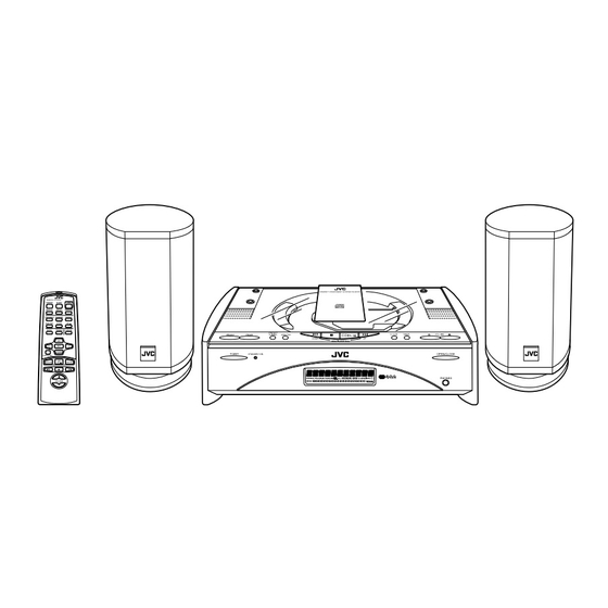
SERVICE MANUAL
COMPACT COMPONENT SYSTEM
FS-SD990 / FS-SD770
REMOTE CONTROL
DIMMER
SLEEP
POWER
AUTO
DISPLAY
PRESET
FM MODE
PROGRAM
RANDOM
REPEAT
DOOR
AHB PRO
SLIDE
CD
BASS
TREBLE
CANCEL
UP
SET
DOWN
FADE MUTING
CD
MD/AUX
FM / AM
VOLUME
REMOTE CONTROL
DIMMER
SLEEP
POWER
DISPLAY
AUTO
FM MODE
PRESET
PROGRAM
RANDOM
REPEAT
DOOR
CD
AHB PRO
SLIDE
BASS
TREBLE
CANCEL
UP
SET
DOWN
FADE MUTING
CD
MD/AUX
FM / AM
VOLUME
The difference between FS-SD550 and FS-SD770 FS-SD990 is only the speaker systems.
The difference between FS-SD770 and FS-SD990 is cabinets of the speaker.
Contents
These models not have adjustment.
Safety Precautions
Important for laser products
Preventing static electricity
Dismantling and assembling
the traverse unit
Disassembly method
Maintenance of laser pickup
Replacement of laser pickup
FS-SD550
FS-SD770, FS-SD990
FS-SD550
1-2
1-3
1-4
1-5
1-6
1-15
1-15
COPYRIGHT
2001 VICTOR COMPANY OF JAPAN, LTD.
FS-SD990 / FS-SD770
Flow of functional operation
unit TOC read
Method of connecting
treatment device wire
Description of major ICs
FS-SD550
Area Suffix
U.S.A
J
Canada
C
1-16
1-17
1-18
No.20947
Apr. 2001
Advertisement

Related Manuals for JVC FS-SD990


Summary of Contents for JVC FS-SD990
- Page 1 FADE MUTING MD/AUX FM / AM VOLUME FS-SD550 The difference between FS-SD550 and FS-SD770 FS-SD990 is only the speaker systems. The difference between FS-SD770 and FS-SD990 is cabinets of the speaker. Contents These models not have adjustment. Safety Precautions Flow of functional operation...
- Page 2 FS-SD990 / FS-SD770 FS-SD550 1. This design of this product contains special hardware and many circuits and components specially for safety purposes. For continued protection, no changes should be made to the original design unless authorized in writing by the manufacturer. Replacement parts must be identical to those used in the original circuits. Services should be performed by qualified personnel only.
- Page 3 FS-SD990 / FS-SD770 FS-SD550 Important for laser products 5.CAUTION : If safety switches malfunction, the laser is able 1.CLASS 1 LASER PRODUCT to function. 2.DANGER : Invisible laser radiation when open and inter 6.CAUTION : Use of controls, adjustments or performance of lock failed or defeated.
- Page 4 FS-SD990 / FS-SD770 FS-SD550 Preventing static electricity Electrostatic discharge (ESD), which occurs when static electricity stored in the body, fabric, etc. is discharged, can destroy the laser diode in the traverse unit (optical pickup). Take care to prevent this when performing repairs.
- Page 5 FS-SD990 / FS-SD770 FS-SD550 Dismantling and assembling the traverse unit Notice regarding replacement of optical pickup Electrostatic discharge (ESD), which occurs when static electricity stored in the body, fabric, etc. is discharged, can destroy the laser diode in the traverse unit (optical pickup). Take care to prevent this when performing repairs to the optical pickup or connected devices.
- Page 6 FS-SD990 / FS-SD770 FS-SD550 Disassembly method <Main body> Removing the CD door (See Fig.1) Remove the four screws A attaching the CD door on the upper side of the body. CD door Fig.1 Removing the rear cover (See Fig.2) Rear cover Piror to performing the following procedure, remove the CD door.
- Page 7 FS-SD990 / FS-SD770 FS-SD550 Removing the front panel assembly (See Fig.4 to 6) Bottom Prior to performing the following procedure, remove the CD door, the rear cover and the side covers. Remove the three screws E on the bottom of the body.
- Page 8 FS-SD990 / FS-SD770 FS-SD550 CD mechanism base assembly Remove the screw G attaching the power amplifier board on the back of the body. Disconnect the wire from connector CN301 and pull the power amplifier board fully outward. Raise the right and left door arms by turning the gear a in the rear of the power amplifier board.
- Page 9 FS-SD990 / FS-SD770 FS-SD550 Door arm Removing the door arm assembly / the Door arm board (R) door arm board (R) and (L) Door arm (See Fig.15 to 20) Prior to performing the following procedure, remove the rear cover, the side covers, the front panel assembly and the CD mechanism base assembly.
- Page 10 FS-SD990 / FS-SD770 FS-SD550 Power amplifier board Door arm assembly Removing the power amplifier board CN191 CN193 (See Fig.21 and 22) CN106 Cord stopper Prior to performing the following procedure, remove Cord the CD mechanism base assembly. stopper Disconnect the wires from connector CN102 and CN193 on the main board and release them from the cord stopper respectively.
- Page 11 FS-SD990 / FS-SD770 FS-SD550 Removing the fan motor assembly (See Fig.25 and 26) Fan motor Prior to performing the following procedure, remove the CD mechanism base assembly. Disconnect the wires from connector CN181 on the main board. Remove the two screws P on the left side of the body.
- Page 12 FS-SD990 / FS-SD770 FS-SD550 <CD mechanism base assembly> Speaker terminal board CD mechanism board CN706 Prior to performing the following procedure, remove the CD mechanism base assembly. CD mechanism Refer to "Dismantling and assembling the CD cover mechanism assembly" on page 1-5 for the treatment of optical pickup.
- Page 13 FS-SD990 / FS-SD770 FS-SD550 Solder the short circuit land on the sub board. CD mechanism assembly Cushion Cushion Disconnect the wire from connector CN605 on the CD mechanism cover main board. Disconnect the sub board from connector CN603 on the main board while peeling off the adhesive tape on the underside of the sub board.
- Page 14 FS-SD990 / FS-SD770 FS-SD550 Removing the jack board (See Fig.35) Jack board Prior to performing following procedure, remove the CD mechanism board. Disconnect the wire from connector CN502 on the Switch board jack board. Remove the two screws V attaching the jack board.
- Page 15 FS-SD990 / FS-SD770 FS-SD550 Maintenance of laser pickup Replacement of laser pickup (1) Cleaning the pick up lens Before you replace the pick up, please try to Turn off the power switch and,disconnect the clean the lens with a alcohol soaked cotton power cord from the ac outlet.
- Page 16 FS-SD990 / FS-SD770 FS-SD550 Flow of functional operation until TOC read Check Point Slider turns REST Play Key Power ON Confirm that the voltage at the pin4 SW ON. of CN605 is "H"/"L"/"H". Automatic tuning of TE offset Check that the voltage at the...
- Page 17 FS-SD990 / FS-SD770 FS-SD550 Method of connecting treatment device wire First short-circuit the pickup circuit before removing the pickup.Then carry out the replacement. Refer to "Dismantling and assembling the traverse unit" on page 1-5. KSM-900AAH Sub board (Reverse side) Shorting Flexible cable When the KSM-900AAH mechanism is used, the expansion cable is used as follows.
- Page 18 FS-SD990 / FS-SD770 FS-SD550 Description of major ICs BD3861FS-X (IC501) : Audio sound control 1. Pin layout 2. Block diagram 0dB~ Middle2 Middle1 Treble1 Treble2 Bass1 Bass2 -70dB f0=1kHz f0=1kHz f0=10kHz f0=10kHz f0=90Hz f0=90Hz Vcc/2 Vcc/2 0dB~ 0dB~ -59dB -59dB...
- Page 19 FS-SD990 / FS-SD770 FS-SD550 LA6541-X(IC602) : Servo Driver 1. Pin Layout & Block Diagram Vref Vin4 Vin3 Level B T L B T L Level RESET shift driver driver shift Level B T L B T L Level Regulator shift...
- Page 20 FS-SD990 / FS-SD770 FS-SD550 UPD780024AGKB19 (IC701) : CPU 1. Pin layout 2. Block diagram 16-bit TIMER/ PORT0 EVENT COUNTER PORT1 8-bit TIMER/ EVENT COUNTER50 8-bit TIMER/ PORT2 EVENT COUNTER51 PORT3 WATCHDOG TIMER 78K/0 WATCH TIMER PORT4 (32K CORE BYTE) SERIAL...
- Page 21 FS-SD990 / FS-SD770 FS-SD550 3. Pin function UPD780024AGKB19 Symbol Function CD door motor control signal 0 output CD door motor control signal 1 output Motor speed control output (L:Normal, H:Slow) BLCTL Back light power supply control output AHB ON/OFF control signal output (L:ON, H:OFF)
- Page 22 FS-SD990 / FS-SD770 FS-SD550 MN662748RPM (IC603) : Digital servo & digital signal processer 1. Pin layout 20 ~ 41 ~ 2.Block diagram AVSS1 LRCKIN(MSEL) 8TIMES AVDD1 BCLK(SSEL) DIGITAL OVER SAMPUNC OUTR SRDATAIN DEEMPHSIS 1BIT DIGITAL FILTER (PSEL) LOGIC IOSEL CLVS...
- Page 23 FS-SD990 / FS-SD770 FS-SD550 3. Pin function MN662748RPM(2/2) Dymbol I/O Function Symbol I/O Function BCLK Not used Tracking error shunt signal output (H:shunt) PLLF2 LRCK Not used TOFS Not used SRDATA WVEL Not used Not used Power supply (Digital) DVDD1...
- Page 24 FS-SD990 / FS-SD770 FS-SD550 LA4905 (IC301) : 2ch BTL power IC 1. Pinlayput 2. Block diagram Vcc(SW) STBY Switching Standby SW regulator block Ripple H.L.S. SW B filter drive A B C D SW E H.L.S. : SW OUT1 Higher...
- Page 25 FS-SD990 / FS-SD770 FS-SD550 AN22000A(IC601):RF & SERVO AMP 1. Pin layout 2. Block diagram OFTR RF IN C.AGC CBDO COFTR RF OUT OFTR RF_EQ 3TENV NRFDET 3TOUT NRFDET SUBT FEOUT SUBT TEOUT TEBPF VDET VDET VREF GCTL TBAL FBAL CDDG VCC 3.
- Page 26 FS-SD990 / FS-SD770 FS-SD550 KIA78S06P-T (IC702) : Regulator 1. Pin layout 2. Block diagram 3 INPUT 1 2 3 1 OUTPUT 2 COMMON TA8409F-W (IC108) : Bridge driver 1. Pin layout 2. Pin function FUNCTION SYMBOL INput terminal Supply voltage terminal for logic...
- Page 27 FS-SD990 / FS-SD770 FS-SD550 LC72136N (IC2) : PLL Frequency synthesizer 1. Pin layout FM/AM LPFOUT LPFIN CLOCK FM/ST/VCO FMIN AM/FM AMIN IFCONT SDIN IFIN 2. Block Phase Reference Detector Driver Charge Pump Swallow Counter Swallow Counter 1/16,1/17 4bit 1/16,1/17 4bit...
- Page 28 FS-SD990 / FS-SD770 FS-SD550 TA2057N (IC1) : FM/AM IF AMP & Detector 1.Block Diagrams IF IN Vstb IF IN QUAD FM OUT AM OUT MPX IN LPF 1 LPF 2 L OUT DIVIDE MUTE DECODE LEVEL AM/FM MONO BUFF IF REQ...
- Page 29 FS-SD990 / FS-SD770 FS-SD550 BA15218F-XE (IC102) : Dual ope. amp. NJM4580D-D (IC101) : Dual ope amp. 1. Pin layout & Block diagram 1. Pin layout & Block diagram A OUT 1 8 V+ OUT1 1 8 Vcc A -IN 2...
- Page 30 FS-SD990 / FS-SD770 FS-SD550 VICTOR COMPANY OF JAPAN, LIMITED AUDIO & COMMUNICATION BUSINESS DIVISION PERSONAL & MOBILE NETWORK BUSINESS UNIT. 10-1,1Chome,Ohwatari-machi,Maebashi-city,371-8543,Japan Printed in Japan No.20947 200104(V)
- Page 31 FS-SD990/FS-SD770 FS-SD550 PARTS LIST [ FS-SD990 ] [ FS-SD770 ] [ FS-SD550 ] * All printed circuit boards and its assemblies are not available as service parts. Area suffix J ----------------------------- U.S.A. C -------------------------- Canada - Contents - Exploded view of general assembly and parts list...
- Page 32 FS-SD990/FS-SD770 FS-SD550 Parts list(General assembly) Block No. M1MM Item Parts number Parts name Q'ty Description Area LV10325-004A FRONT PANEL FS-SD990 LV10325-002A FRONT PANEL FS-SD770/SD550 LV31677-201A PUSH BUTTON 1 ABS/PLATING QYSDSF2608Z SCREW GN30006-001A SPACER GN30001-002A LENS FS-SD770/SD550 GN30001-004A LENS FS-SD990 LV31679-001A...
- Page 33 FS-SD990/FS-SD770 FS-SD550 Parts list(General assembly) Block No. M1MM Parts list(General assembly) Block No. M1MM Item Parts number Parts name Q'ty Description Area Item Parts number Parts name Q'ty Description Area QYSBSF3010Z SCREW QYSPSFG2605N SCREW DOOR BASE+ARM LV31705-002A HEAT SINK QYSPSPG3006Z SCREW SAFT 1+G.BASE...
- Page 34 FS-SD990/FS-SD770 FS-SD550 Exploded view of general assembly and parts list Block No. DI801...
- Page 35 FS-SD990/FS-SD770 FS-SD550 Electrical parts list(Main board) Block No. 01 Item Parts number Parts name Remarks Area Item Remarks Parts number Parts name Area NCB21HK-223X C CAPACITOR C1103 QFVJ1HJ-563Z MF CAPACITOR FS-SD990 NCB21HK-102X C CAPACITOR C1103 QFN31HJ-563Z M CAPACITOR FS-SD770/SD550 NCB21EK-473X...
- Page 36 FS-SD990/FS-SD770 FS-SD550 Electrical parts list(Main board) Block No. 01 Item Remarks Item Parts number Parts name Remarks Area Parts number Parts name Area C3101 QTE1V06-106Z E CAPACITOR D8025 MTZJ10C-T2 ZENER DIODE FS-SD770/SD550 C3102 QDGB1HK-102Y C CAPACITOR D8031 SELU1E56BM FS-SD770/SD550 C3103...
- Page 37 FS-SD990/FS-SD770 FS-SD550 Electrical parts list(Main board) Block No. 01 Item Remarks Parts number Parts name Area Item Parts number Parts name Remarks Area Q8003 DTA114EKA-X DIGITAL.TRANSIS R1208 NRSA02J-432X MG RESISTOR Q8101 2SD2114K/VW/-X CHIP TRANSISTOR R1209 NRSA02J-153X MG RESISTOR Q8201 2SD2114K/VW/-X...
- Page 38 FS-SD990/FS-SD770 FS-SD550 Block No. 01 Electrical parts list(Main board) Item Parts number Parts name Remarks Area Item Remarks Parts number Parts name Area R1933 NRSA02J-681X MG RESISTOR CD6.5 S8006 QSW0683-001Z PUSH SWITCH CLOCK R1934 NRSA02J-152X MG RESISTOR CD6.5 S8007 QSW0683-001Z...
- Page 39 FS-SD990/FS-SD770 FS-SD550 Electrical parts list(CD board) Block No. 02 Item Parts number Parts name Remarks Area Item Parts number Parts name Remarks Area CN501 QGF1201F3-08 CONNECTOR TO MAIN C6031 QEKC1AM-227Z E CAPACITOR 220MF 20% 10V CN502 QGA2001C1-04 4P PLUG ASSY...
- Page 40 FS-SD990/FS-SD770 FS-SD550 Electrical parts list(CD board) Block No. 02 Item Remarks Item Parts number Parts name Remarks Area Parts number Parts name Area D6062 1SS355-X DIODE R5208 NRSA63J-222X MG RESISTOR L/O MUTE D6063 1SS355-X DIODE R5209 NRSA63J-563X MG RESISTOR S.W.OUT D6500 MTZJ8.2B-T2...
- Page 41 FS-SD990/FS-SD770 FS-SD550 Electrical parts list(CD board) Block No. 02 Item Remarks Parts number Parts name Area Item Parts number Parts name Remarks Area R6254 NRSA63J-104X MG RESISTOR R7061 NRSA63J-103X MG RESISTOR R6256 NRSA63J-564X MG RESISTOR R7062 NRSA63J-222X MG RESISTOR R6257...
- Page 42 FS-SD990/FS-SD770 FS-SD550 < M E M O > 3-12...
- Page 43 FS-SD990/FS-SD770 FS-SD550 Packing materials and accessories parts list Block No. FS-SD550 Block No. A3, A4 A2,A8,A9,A10, A11,A12 3-13...
- Page 44 FS-SD990/FS-SD770 FS-SD550 Packing materials and accessories parts list Block No. FS-SD770/FS-SD990 Block No. A3, A4 A2, A8, A9,A10 A11,A12 3-14...
- Page 45 BATTERY BT-51018-2 WARRANTY CARD BT-51020-2 J=REGIST CARD A 10 BT-20044G WARRANTY CARD A 11 BT-52004-1 WARRANTY CARD A 12 BT-20071B JVC CENTER LIST A 13 FSSD550K-SPBOX SPEAKER BOX SP-FSSD550 FSSD770K-SPBOX SPEAKER BOX SP-FSSD770 FSSD990K-SPBOX SPEAKER BOX SP-FSSD990 A 14 LV10497-001A...
- Page 46 FS-SD990 / FS-SD770 FS-SD550 SIGL TU5V SIGR AMOSC IC301 AMRF FM IF/DET/MPX POUT OUT1 OUT1 FILTER IC101 POWER AM RF/IF/DET OUT2 OUT2 TUNERL AHBNF AMIN IFOUT/CONT SIGL TUNERR SIGR RFIN FMIN TUST,TUDATA W3901 US5V TUCK,Vt/FM+B CN193 SW10V CN101 IC102 CN501...
- Page 47 FS-SD990 / FS-SD770 FS-SD550 < M E M O >...
- Page 48 FS-SD990 / FS-SD770 FS-SD550 Standard schematic diagrams CD servo control section J6001 GP1FA550TZ C6015 R6005 180k 0.022 TBAL R6006 270k C6016 FBAL 0.022 C6159 R6007 R6009 R6012 8.2K C6020 R6025 C6019 C6017 R6024 470P 0.022 330P R6008 390K VDET R6028 2.2K...
- Page 49 FS-SD990 / FS-SD770 FS-SD990 / FS-SD770 FS-SD550 FS-SD550 Power supply & main circuit section Q1101 2SD2114K/VW/-X IC301 R1111 LA4905 LF111 QQR0590-001 R1107 R1108 4.3k R1118 C1110 LF311 J3001 QQR0797-002 0.001 C1104 QNB0092-001 R1110 R1101 1.2K R1103 C1103 0.056 R1201 1.2K 220k 0.056...
- Page 50 FS-SD990 / FS-SD770 FS-SD550 System control section R8302 2.2K R8301 2.2K L8101 QQL231K-470Y L8201 QQL231K-470Y J8301 C8101 R8101 Q8101 QNS0162-001 K8301 220/10 2SD2114K/VW/-X R8103 QQR0601-001Z 2.7K R8005 Q8201 2SD2114K/VW/-X R8006 R8203 IC801 GP1U271X 2.7K C8003 0.022 Q8003 R8010 100K R8201...
- Page 51 FS-SD990 / FS-SD770 FS-SD990 / FS-SD770 FS-SD550 FS-SD550 Tuner section 0.01 QNB0014-001 QQR0796-001 QAU0097-001 0.001 0.047 0.01 3.9K 0.01 0.022 TA2057N 3.3/50 3.9K 0.022 3.3K 2.2K 0.0039 QQL231K-221Y 0.001 0.047 220P 47/16 0.047 LC72136N 100P 100P 150P Tuner signal Note:/tr/s/jsc/sd550/LVS200296_GNS10002-001A 6/8...
- Page 52 FS-SD990 / FS-SD770 FS-SD550 Printed circuit boards Power IC board Main board C1108 R1113 R1307 R1114 W3001 R1924 B1021 IC102 R1213 R1215 R1214 C1921 C1209 R3107 CN103 R3101 R1926 R3102 R3202 D1911 R3201 R1309 C1925 CN104 C1922 D1304 R3207 R1311...
- Page 53 FS-SD990 / FS-SD770 FS-SD990 / FS-SD770 FS-SD550 FS-SD550 Line board (Forward side) Sub board (forward side) Line board (Reverse side) LVA10225-01A1 CN606 W8004 C5306 W5001 W5001 C5305 W8004 S8021 CN501 CN501 S8021 R5104 R5204 R5211 C5102 IC501 R5111 C5102 C5202...
Need help?
Do you have a question about the FS-SD990 and is the answer not in the manual?
Questions and answers