
Related Manuals for Sonotec BS40


Summary of Contents for Sonotec BS40
- Page 1 Operating Manual BS40 Broadband structure-borne sound sensor for the SONAPHONE handheld unit Translation of the German Original Revision: 1.1 | 2023-04-27...
-
Page 2: Table Of Contents
Operating Manual | Content BS40 Content Introduction ........................3 Notes on this documentation ..................3 Representations in this documentation ................ 3 Identification of warning instructions ................4 Safety instructions ......................5 Introduction ........................5 Basic hazards ........................5 Personnel and qualifications ..................6 Safety-conscious working practices ................ -
Page 3: Introduction
Operating Manual | 1 Introduction BS40 1 Introduction This section is intended to explain function, structure and representations of this documentation to simplify handling of this documentation. Notes on this documentation Purpose This documentation constitutes an integral part of the product and contains important advice on safe operation as well as all information on intended and efficient use. -
Page 4: Identification Of Warning Instructions
Operating Manual | 1 Introduction BS40 1.3 Identification of warning instructions Classes of danger, signal words and colors This documentation contains warnings regarding hazards of different classifications. These classes are characterized by signal words and colors. They include the following:... -
Page 5: Safety Instructions
Operating Manual | 2 Safety instructions BS40 2 Safety instructions This section contains safety information relating to the protection of persons as well as safe and fault-free operation. All user groups of the product must be aware of and follow these safety provisions. -
Page 6: Personnel And Qualifications
Operating Manual | 2 Safety instructions BS40 2.3 Personnel and qualifications Basic requirements The product must only be used by operators that have completely read and understood the safety instructions and all documents of the user documentation. Personnel undergoing training or instructions or persons taking part in general vocational training programs may only operate the device under the continuous supervision of operating or technical personnel. -
Page 7: Use Of The Product
Do not use the product and its accessories if they display functional errors and/or visible damage. • Only connect the product to approved equipment received from SONOTEC GmbH or its sales partners. • The product adheres to the protection class given in the technical specification and is not protected against water. -
Page 8: Modifications And Alterations
Spare parts and accessories Spare parts and accessories must comply with the technical requirements specified by SONOTEC GmbH and its suppliers. Whenever original parts are used, compliance is given. No alterations to the software Do not alter the supplied software or commission software alterations to third parties. The software may not be disassembled, decrypted or decompiled in full or in part. -
Page 9: Description Of The Sensor
3.2 Prohibited use Any use not approved by SONOTEC GmbH is prohibited and may lead to injury or damage to property. SONOTEC GmbH accepts no liability for damage caused by prohibited use of the product. -
Page 10: Sensor Construction
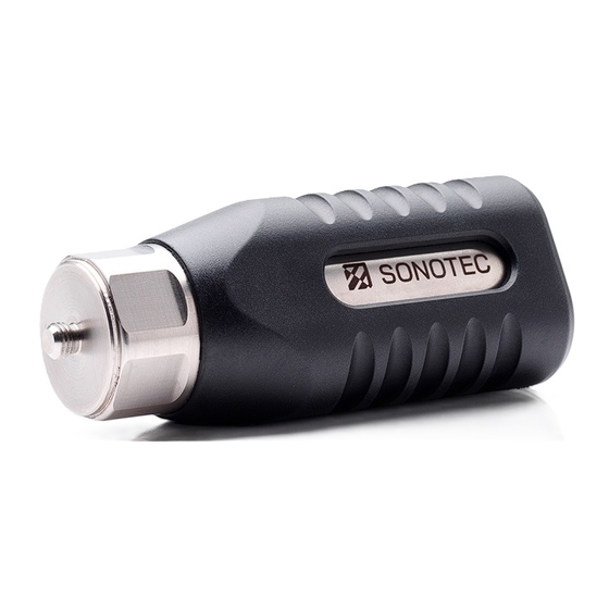
Operating Manual | 3 Description of the sensor BS40 3.3 Sensor construction Sensor elements Figure 1: Sensor elements of the BS40 Component Ultrasonic transducer with UNF ¼" 28 threaded pin Status LED • green light: sensor is activated • red light: sensor is in boot mode •... -
Page 11: Sensor Identification
Operating Manual | 3 Description of the sensor BS40 3.4 Sensor identification Identification plate Figure 2: Identification plate with its components Identification CE marking Manufacturer’s address Serial number Disposal symbol (see "7 Disposal", page 23) 11 / 25 Revision: 1.1 | 2023-04-27... -
Page 12: Accessories
Operating Manual | 3 Description of the sensor BS40 3.5 Accessories Intensity and behavior of ultrasonic signals depend on factors such as the process during which they are generated. Measurement value recordings with high signal quality are necessary for valid conclusions on system conditions. Signal quality also depends on a number of factors. - Page 13 Operating Manual | 3 Description of the sensor BS40 Mounting pad Application • Fitting a designated coupling position for magnetic or screwed sensor coupling for recurring temporary or semi-stationary tests • Including UNF ¼" 28 internal thread for screwing in the sensor...
-
Page 14: Operation Of The Sensor
Operating Manual | 4 Operation of the sensor BS40 4 Operation of the sensor This section contains descriptions and instructions for operating the sensor and using it in combination with the SONAPHONE handheld unit. CAUTION Risk of crushing by magnetic foot or general-purpose magnet! The magnetic foot and the general-purpose magnet exhibit a very strong magnetic force. -
Page 15: Preparing The Point Of Measurement
Operating Manual | 4 Operation of the sensor BS40 4.2 Preparing the point of measurement For correct and reproducible measurement results during recurring measurements, the point of measurement may be prepared as follows depending on the application: Ensure that the surface is clean and free of scratches. -
Page 16: Magnetic Coupling For Temporary Measurements
Operating Manual | 4 Operation of the sensor BS40 4.3.1 Magnetic coupling for temporary measurements Coupling methods For temporary measurements, the sensor may be coupled magnetically with the point of measurement. Depending on the local conditions and the particular application, one of the... - Page 17 Operating Manual | 4 Operation of the sensor BS40 Coupling Screw the required magnet on the sensor and hand-tighten. Push the protective pad sideways to remove it from the magnet. Carefully position the sensor on the point of measurement by placing the edge of the magnet.
-
Page 18: Uncoupling
Operating Manual | 4 Operation of the sensor BS40 Uncoupling Carefully tilt the sensor from the point of measurement. Carefully pull the sensor from the point of measurement. Carefully push the protective pad sideways on the magnet. 18 / 25... -
Page 19: Screwed Coupling For Semi-Stationary Measurements
Operating Manual | 4 Operation of the sensor BS40 4.3.2 Screwed coupling for semi-stationary measurements Coupling methods For semi-stationary measurements, the sensor may be screwed into a prepared point of measurement. Depending on the local conditions and the particular application, one of the... -
Page 20: Cleaning And Maintenance
ATTENTION Check the compatibility of used cleaning agents! The compatibility of all cleaning agents with used materials and colors must be confirmed and approved by SONOTEC GmbH or the respective supplier. Unsuitable cleaning agents Do not clean the product with: •... -
Page 21: Technical Data
-10 … +65 °C Storage temperature -20 … +65 °C (up to 40 °C at 90 % humidity) Protection type IP50 Order details Scope of delivery • Broadband structure-borne sound sensor BS40 • Calibration certificate 21 / 25 Revision: 1.1 | 2023-04-27... - Page 22 Operating Manual | 6 Technical data BS40 Technical drawing 22 / 25 Revision: 1.1 | 2023-04-27...
-
Page 23: Disposal
Operating Manual | 7 Disposal BS40 7 Disposal Recycling and taking back of used equipment Electrical and electronic devices may pose a risk to health and the environment if disposed of incorrectly. They cannot therefore be disposed of as domestic waste according to WEEE Directive 2012/19/EU (Waste Electrical and Electronic Equipment Directive). -
Page 24: Warranty
Warranty During the warranty period, SONOTEC GmbH will eliminate all deficiencies caused by material or manufacturing faults free of charge. SONOTEC GmbH will at its own discretion offer warranty by reparation or replacement of faulty products. Exceptions Internal accumulators as well as damage caused by unintended use, by wear or by manipulation of the product are exempt from warranty. -
Page 25: Manufacturer Information
© SONOTEC GmbH All rights reserved. All contents of this document are property of SONOTEC GmbH and are protected by copyright. Duplication, modification and/or distribution in any form, particularly for reprint, for photographic, mechanical or electronic reproduction or in the form of saving in data processing systems or data networks is forbidden without written approval by SONOTEC GmbH.
Need help?
Do you have a question about the BS40 and is the answer not in the manual?
Questions and answers