
Related Manuals for Sonotec SONOFLOW IL.52/3 V2.0


Summary of Contents for Sonotec SONOFLOW IL.52/3 V2.0
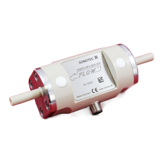
- Page 1 Ultrasonic Flow Sensor SONOFLOW IL.52 V2.0 ® User Documentation Including Technical Data Sheet Operating Manual Certificates...
- Page 2 (This page has been deliberately left empty)
- Page 3 Due to the current, frequency and switching outputs industrial dosing applications can be supported. The RS485 interface (SONOTEC ® protocol; MODBUS ® software settings) allows bus operation of up to 12 sensors in rough industrial environments.
- Page 4 Required: via cable / housing (mounting screws) Interfaces • Current output for flow rate: 0/4 … 20 mA • Frequency output for flow rate: 0 … 20 kHz, 5 V digital • RS485 interface: bus-capable (SONOTEC protocol, optional MODBUS ® ®...
- Page 5 Input Frequency output 5 V Load min. 5 kΩ Ground Ground RS485 interface SONOTEC protocol: Half-duplex operation / 115.200 baud / no parity / 1 ® stop bit / no handshaking (MODBUS via software settings) ® NOTE: Please find the description of the serial protocol for details (upon request).
- Page 6 SONOFLOW ® IL.52/3 V2.0 Technical Data Sheet Ultrasonic Flow Sensor Digital input Freely configurable: for example for zero point calibration of flow or start dosing processes Voltage resistant up to 30 V SENSOR HOST Digital input Ground Ground Protection class IP65 Cleaning and Maximum liquid temperature: temporarily +145 °C;...
- Page 7 Technical Data Sheet SONOFLOW ® IL.52/3 V2.0 Ultrasonic Flow Sensor Electrical connection Male connector Female connector (at the sensor) (at the cable) M12 connecting cable Color Connection Assignment White Ground Brown Operating voltage +12 ... 30 VDC Green Current output (0/4 … 20 mA) Yellow RS485 B Grey...
- Page 8 Drawings are not to scale. Dimensions in mm, unless otherwise specified. Information is subject to change without notice. HEADQUARTERS GERMANY AMERICAS SONOTEC GmbH SONOTEC US Inc. Nauendorfer Str. 2 Tel.: +49 (0)345 / 133 17- 0 190 Blydenburgh Rd Phone: +1 631 / 415 4758 06112 Halle (Saale) sales_eu@sonotec.de...
- Page 9 Ultrasonic Flow Sensor Type SONOFLOW IL.52 V2.0 Operating Manual...
- Page 10 © SONOTEC Ultraschallsensorik Halle GmbH All rights reserved. Revision: 1.0; Date: 2018-10-26 Information is subject to change without notice!
-
Page 11: Table Of Contents
Operating Manual SONOFLOW IL.52 V2.0 Contents Notes on operating manual ........................5 General ............................5 Symbols used ..........................5 Safety regulations ..........................7 User qualifications .......................... 7 General safety information ......................8 Sensor description ..........................9 Intended use........................... 9 Construction ........................... 9 Measuring method and functioning .................... - Page 12 SONOFLOW IL.52 V2.0 Operating Manual (This page has been deliberately left empty) Revision: 1.0; Date: 2018-10-26...
-
Page 13: Notes On Operating Manual
Operating Manual SONOFLOW IL.52 V2.0 Notes on operating manual 1.1 General Thank you for choosing a sensor from the SONOFLOW IL.52 V2.0 series. This manual forms part of the sensor and should therefore be stored in its immediate vicinity where it can be accessed by all operators at any time. It contains all the information needed to ensure proper and efficient use, along with all the instructions to ensure safe operation of the SONOFLOW IL.52 V2.0. - Page 14 SONOFLOW IL.52 V2.0 Operating Manual (This page has been deliberately left empty) Revision: 1.0; Date: 2018-10-26...
-
Page 15: Safety Regulations
Operating Manual SONOFLOW IL.52 V2.0 Safety regulations 2.1 User qualifications The SONOFLOW IL.52 V2.0 may only be installed and operated by users who have read and understood the entire operating manual and the Technical Data Sheet. Make sure to read all safety regulations. NEVER CHANGE SETTINGS of the sensor before you have saved all parameters with the help of SONOFLOW Monitor. -
Page 16: General Safety Information
SONOFLOW IL.52 V2.0 Operating Manual 2 Safety regulations 2.2 General safety information The SONOFLOW IL.52 V2.0 is a state of the art product that complies with all applicable safety regulations. All sensors are factory tested and delivered in a safe condition for operation. The following safety instructions apply: Incorrect installation and use of the SONOFLOW IL.52 V2.0 sensor and its components can present a hazard for the user. -
Page 17: Sensor Description
Any use other than the designated use is prohibited and can result in personal injury or damage to property. SONOTEC Ultraschallsensorik Halle GmbH accepts no liability for damage, including to third parties, caused by improper handling of the sensors. -
Page 18: Measuring Method And Functioning
SONOFLOW IL.52 V2.0 Operating Manual 3 Sensor description With respect to material resistance the following sensor versions are available: Seals (in contact with the medium) Order number Viton 200 08 0001 FFKM 200 08 0044 Table 2: Versions of SONOFLOW IL.52 V2.0 3.3 Measuring method and functioning The ultrasonic sensor works with the time-of-flight measurement principle. -
Page 19: Installation And Commissioning
Operating Manual SONOFLOW IL.52 V2.0 Installation and commissioning The SONOFLOW IL.52 V2.0 is intended as component to be integrated into devices or machines. The sensor is mechanically and electrically incorporated into the customer control unit. 4.1 Attaching the Sensor SONOFLOW IL.52 V2.0 The geometric layout always determines flow characteristics in a fluid system. -
Page 20: Output Configuration And Settings
SONOFLOW IL.52 V2.0 Operating Manual Output Configuration and Settings The settings can be adapted for special measuring tasks using the SONOFLOW Monitor (optional accessory). 5.1 Current output for flow rate The default settings for current output are: Parameter Default setting Further options (via SONOFLOW Monitor) Configuration... -
Page 21: Switching Output
(sensor transmits measuring data cyclically; interval adaptable) Table 6: Default settings for RS485 interface Further information you will find in the document “Concept of Serial Communication” for SONOTEC Flow Sensors. Contact our Service. Revision: 1.0; Date: 2018-10-26... -
Page 22: Digital Input
SONOFLOW IL.52 V2.0 Operating Manual 5 Output Configuration and Settings 5.5 Digital input Parameter Default setting Further options (via SONOFLOW Monitor) Configuration Flow Zero Adjust OFF | Reset Volume | Restart Option to Zero adjust Deactivated While input is active Table 7: Default settings for digital input Revision: 1.0;... -
Page 23: Operating The Sensor
Operating Manual SONOFLOW IL.52 V2.0 Operating the sensor Incorrect use of the sensors SONOFLOW IL.52 V2.0 and their components can have an impact on the sensor functionality. Depending on the application this can have unforeseeable consequences. Prevent the lateral plates from contacting electrically conductive parts or components. -
Page 24: Troubleshooting And Maintenance
Try to remove the gas by maximum flow, by changing the sensor position or by light tapping on the sensor! Device Fault Contact SONOTEC! Table 8: Default values for error output The sensors of SONOFLOW IL.52 V2.0 series are maintenance free. -
Page 25: Disposal
Operating Manual SONOFLOW IL.52 V2.0 Disposal Electrical and electronic equipment can pose serious health and environmental risks if it is not properly disposed of. For this reason it must not be disposed of in domestic waste according to WEEE directive 2012/19/EU (Waste Electrical and Electronic Equipment Directive) but separately at designated collection points or has to be sent back to the manufacturer. - Page 26 SONOFLOW IL.52 V2.0 Operating Manual Subject to technical modifications! MANUFACTURER USA CONTACT DETAILS SONOTEC SONOTEC US Inc. Ultraschallsensorik Halle GmbH Tel.: +49 (0)345/133 17- 0 190 Blydenburgh Rd Tel.: +1 631/415 4758 Nauendorfer Str. 2 sonotec@sonotec.de Suite 8, 2 Floor sales@sonotecusa.com...
- Page 29 (This page has been deliberately left empty)
- Page 30 © SONOTEC GmbH All rights reserved. The content of this manual is the property of SONOTEC Ultraschallsensorik Halle GmbH and is protected by copyright. Duplication and distribution in any form, particularly reprinting, photographic, mechanical or electronic reproduction, or in the form of storage in data processing systems or data networks, is prohibited without the consent of the copyright holder.
Need help?
Do you have a question about the SONOFLOW IL.52/3 V2.0 and is the answer not in the manual?
Questions and answers