Table of Contents
Advertisement
Quick Links
Advertisement
Table of Contents

Related Manuals for Epson EB-810E


Summary of Contents for Epson EB-810E
- Page 1 Installation Guide...
-
Page 2: About This Installation Guide
About This Installation Guide Contents of this Guide This guide explains how to install an ultra-short throw projector (EB-810E/EB-815E) using the setting plate (ELPMB75). Tightening Torques for Screws The following provides the tightening torque for each screw. Screw Size Recommended Tightening Tor- que N/m 1.1 ±... -
Page 3: Table Of Contents
Contents Adjusting the Position of the Projected Image About This Installation Guide ........46 Contents of this Guide . -
Page 4: Introduction
Introduction Using the Product Safely For your safety, read all the instructions in this guide before using this product. Incorrect handling that ignores instructions in this guide could damage this product or could result in personal injury or property damage. Keep this installation guide at hand for future reference. -
Page 5: Package Contents
Introduction Package Contents Confirm that you have all necessary items before beginning installation. Setting Plate Main Mount M4 x 12mm M4 x 12mm M4 x 12mm Part name End cap Adjustment unit Arm unit Wall plate Wall plate cover Hexagonal axis... -
Page 6: Accessories
Introduction Accessories Part Name Application Template sheet Attach this to the wall before attaching the wall plate, and use it to drill neces- sary holes. Mini PC plate Attach this to the wall plate when in- stalling a mini PC or stick PC. Mini PC belt Secure the PC to the plate when at- taching a mini PC or a stick PC that can-... -
Page 7: Necessary Items
Introduction Part Name Application M6 x 20 mm hexagon Secure the arm unit to the wall plate. shoulder head bolt with washer/spring washer (x1) M6 x 20 mm cross recessed head shoulder screws with plastic washers (x3) M3 x 6 mm cross recessed Secure the mini PC plate to the wall head shoulder screws (x4) plate. -
Page 8: Figures Of Installation Dimensions
Introduction Figures of Installation Dimensions 100mm 350mm 100mm Caution When installing the projector, make sure there is a gap between the wall and the projector's air exhaust and intake vents. (See figure above) Leaving a gap of approximately 100 mm from the ceiling to the top of the wall plate makes it easier to install and remove the projector. - Page 9 Introduction If you cannot set the Blend Range to 600, you can set it to less than 600. If it is set to less than 600, black bars may appear on the left and right sides of the image.
-
Page 10: Connection Figure
Introduction Connection Figure Connecting Multiple Projectors You need the following cables when installing multiple projectors. If you need to use other cables, check the User's Guide. You can install two to four projectors side-by-side. The following image is an example of connecting three projectors. (Max 5m) HDMI1 (Max 5m) -
Page 11: Notes On Installing The Setting Plate
Use M10 or 3/8 inch x 60 mm nuts and bolts. Nuts and bolts smaller than M10 or 3/8 inch x 60 mm could cause the setting plate to fall. Epson accepts no responsibility for any damage or injury caused by lack of wall strength or inadequate installation. - Page 12 If any abnormalities occur with this product, immediately disconnect the cables from the product, and then contact your local dealer or the nearest Epson service call center. Continuing to use the product in an abnormal condition could cause a fire, electric shock, or visual...
- Page 13 Installing the Setting Plate Warning Laser warning labels have been attached to the inside and outside of the projector. Internal External Do not look into the laser beam emitted from the projection lens while projecting. (Based on IEC/ EN60825-1:2014)
- Page 14 Installing the Setting Plate Warning Never open any cases on the projector. Electrical voltages inside the projector can cause severe injury. Do not look directly into the projector’s light source. Possibly hazardous optical radiation emitted from this product. Eye injury may result. Caution Do not install this product in a location where the operating temperature for your projector model may be exceeded.
-
Page 15: Cautions On The Installation Location Of The Setting Plate
Installing the Setting Plate Cautions on the Installation Location of the Setting Plate Warning Do not install in a location subject to oily smoke or smoke for events. If oils and so on stick to the slide plate fixing part of the projector, the case may crack and cause the projector to fall, resulting in personal injury or property damage. - Page 16 Installing the Setting Plate Caution When installing two or more projectors in parallel, leave a gap of at least 750mm between the projectors. 750mm If you cannot secure a gap of approx. 750mm, install a partition to block the heat vented from the projector's air exhaust vent.
-
Page 17: Setting Plate Specifications
Installing the Setting Plate Setting Plate Specifications Item Specification Setting plate mass (arm unit, hexagonal axis, adjustment unit, wall plate, wall Approx. 9.5 kg plate cover, end cap) Maximum load capacity 15.0 kg... -
Page 18: External Dimensions
Installing the Setting Plate External Dimensions 549.9 LENS CENTER 70.4 255.3 97 - 424... - Page 19 Installing the Setting Plate 167.2 355.1 387 - 655.5 41.1 35.7 48.2 339 - 666 Φ6 Φ5...
-
Page 20: Adjustment Range
Installing the Setting Plate 8 x M3 23.2 35.7 Adjustment Range Vertical slide... -
Page 21: Horizontal Slide
Installing the Setting Plate Horizontal slide Forward/backward slide 0 - 266... -
Page 22: Mini Pc Installation Plate
Installing the Setting Plate Mini PC Installation Plate 14.7 22.7 35.2 8 x Φ5 4 x Φ3.8 145.5 21.7 Item Specification Screw holes for installing PC (VESA compliant) 75 mm x 75 mm 100 mm x 100 mm Supported PC sizes Within 150 mm x 150 mm x 44 mm Supported PC weight 0.7 kg or less... -
Page 23: Installing The Setting Plate
Installing the Setting Plate Installing the Setting Plate Follow the work flow below to install the setting plate. Route the cables before installing the wall mount according to your installation environment. Remove the feet from the projector (3 places in total), and then attach the rubber caps to the front foot section. -
Page 24: Attaching The Mount
Installing the Setting Plate Attaching the Mount Determining the installation position (projection distance tables) Determine the installation position of the wall plate according to the size of the screen (S) you want to project on to. See the following figure to check the values from a to d. This is the value when the arm unit is in the middle of the wall plate (see in the following illustration). - Page 25 Installing the Setting Plate See the following for the values for c and d when projecting at an aspect ratio of 16:6 or 21:9. • c1/d1: When the Screen Position is in the center • c2/d2: When the Screen Position is at the top...
- Page 26 Installing the Setting Plate 16:9 projected image [Unit: mm] 100 " 221 × 125 101 " 224 × 126 102 " 226 × 127 103 " 228 × 128 104 " 230 × 130 105 " 232 × 131 106 " 235 ×...
- Page 27 Installing the Setting Plate 131 " 290 × 163 132 " 292 × 164 133 " 294 × 166 134 " 297 × 167 135 " 299 × 168 136 " 301 × 169 137 " 303 × 171 138 " 306 ×...
- Page 28 Installing the Setting Plate 16:10 projected image [Unit: mm] 93 " 200 × 125 94 " 202 × 127 95 " 205 × 128 96 " 207 × 129 97 " 209 × 131 98 " 211 × 132 99 " 213 ×...
- Page 29 Installing the Setting Plate 123 " 265 × 166 124 " 267 × 167 125 " 269 × 168 126 " 271 × 170 127 " 274 × 171 128 " 276 × 172 129 " 278 × 174 130 " 280 ×...
- Page 30 Installing the Setting Plate 4:3 projected image [Unit: mm] 82 " 167 × 125 83 " 169 × 126 84 " 171 × 128 85 " 173 × 130 86 " 175 × 131 87 " 177 × 133 88 " 179 ×...
- Page 31 Installing the Setting Plate 112 " 228 × 171 113 " 230 × 172 114 " 232 × 174 115 " 234 × 175 116 " 236 × 177 117 " 238 × 178 118 " 240 × 180 119 " 242 ×...
- Page 32 Installing the Setting Plate 16:6 projected image [Unit: mm] 93 " 221 × 83 94 " 224 × 84 95 " 226 × 85 96 " 228 × 86 97 " 231 × 87 98 " 233 × 87 99 " 235 ×...
- Page 33 Installing the Setting Plate 123 " 293 × 110 124 " 295 × 111 125 " 297 × 111 126 " 300 × 112 127 " 302 × 113 128 " 304 × 114 129 " 307 × 115 130 " 309 ×...
- Page 34 Installing the Setting Plate 21:9 projected image [Unit: mm] 95 " 222 × 95 96 " 224 × 96 97 " 226 × 97 98 " 229 × 98 99 " 231 × 99 100 " 233 × 100 101 " 236 ×...
- Page 35 Installing the Setting Plate 125 " 292 × 125 126 " 294 × 126 127 " 296 × 127 128 " 299 × 128 129 " 301 × 129 130 " 304 × 130 131 " 306 × 131 132 " 308 ×...
-
Page 36: Attaching The Adjustment Unit To The Projector
Installing the Setting Plate Attaching the adjustment unit to the projector Loosen the M4 bolt on the adjustment unit, and then align the marks for each part When the position is correct, tighten the M4 bolt. Secure the adjustment unit to the base of the projector with the M4 x 12 mm bolts (x4) supplied... -
Page 37: Install The Wall Plate On The Wall
Installing the Setting Plate Install the wall plate on the wall Attach the template sheet to the wall Attach the template sheet according to the installation position that you confirmed using the projection distance table ( p.23). Align the center position of the screen being projected with Image Center A on the Template sheet. Drive a commercially available M10 screw into the position of the temporary screw hole for the wall plate Leave a gap of 6 mm or more between the wall and the screw head. - Page 38 Installing the Setting Plate Determine the positions for the mounting holes for the wall plate From the screw holes shown in the figure below, secure at least four points at the top, bottom, left, and right for optimum balance. Drill the holes in the wall Drill diameter: 10.5 mm (M10) or 10 mm (3/8 inches) Pilot hole depth: 45 mm Anchor hole depth: 40 mm...
-
Page 39: Install The Arm Unit On The Wall Plate
Installing the Setting Plate Use commercially available M10 or 3/8 inch x 60 mm anchor bolts to secure the wall plate to the holes you drilled in step 4 Install the arm unit on the wall plate Loosen the M4 x 12 mm bolts (x2) and extend the arm slide on the arm unit Adjust the scale on the slider to the combined distance of the value for (b) confirmed in the projection distance table ( p.23) and the thickness of the projection surface (x). - Page 40 Installing the Setting Plate Insert the hexagonal axis into the arm unit Route the necessary cables through the arm unit Warning Do not hang the rest of the cables over the arm unit. They could fall and cause an accident. Make sure that cable ports for connecting to peripheral devices such as mini PCs are routed so that they come out of the lower part of the arm unit and not through walls.
- Page 41 Installing the Setting Plate Attach the arm unit to the wall plate Insert the hexagonal axis until the tip extends slightly out of the top of the wall plate and the other end connects to the bottom of the wall plate. Caution Take care not to trap the cables between the arm unit and the wall plate.
- Page 42 Installing the Setting Plate Temporarily secure the arm unit Secure three points with the M6 screws supplied (x3). Adjust the vertical slide with the open-ended spanner to align the marks on the wall plate and the arm unit.
- Page 43 Installing the Setting Plate Tighten the M6 bolt (x1) to secure the arm unit in position...
-
Page 44: Attach The Adjustment Unit To The Arm Unit
Installing the Setting Plate Attach the adjustment unit to the arm unit Check the installation position for the adjustment unit The installation position is marked on the arm unit. Install at an appropriate position according to the size of the screen you want to project on to. •... -
Page 45: Attaching Peripheral Devices
Installing the Setting Plate Secure the adjustment unit to the arm unit with the M4 x 12 mm bolts (x4) supplied Connect the cables to the projector Connect the power cord last. Attaching peripheral devices Attach the mini PC or stick PC to the mini PC plate, and secure it to the left or right side of the wall plate. Attach it so that the air exhaust vents of the PC are not blocked. - Page 46 Installing the Setting Plate Secure the mini PC plate to the wall plate using the M3 x 6 mm screws (x4) supplied. Place the PC on the lower edge of the mini PC plate, and secure it with the belt When securing with screws Depending on the shape of the mini PC and the orientation of the screw holes, the order in which parts are installed differs.
-
Page 47: Adjusting The Position Of The Projected Image
Installing the Setting Plate • Secure the mini PC plate to the wall plate using the M3 x 6 mm screws (x4) supplied, and then install the PC. Adjusting the Position of the Projected Image You can use any of the following methods to adjust the position of the projected image. - Page 48 Installing the Setting Plate When multiple projectors are installed in the same room, we recommend that you set projector IDs to prevent remote control interference. Turn on a projector and set the ID number for the projector in Installation > Projector ID. When you want to operate a specific projector, hold down the [ID] button on the remote control and press the button with the same number as the projector ID.
-
Page 49: Preparations Before Adjusting
Installing the Setting Plate • Images are not stable immediately after turning on the projector. After starting projection, wait for at least 30 minutes before adjusting the image. • Install and adjust the projector at a room temperature that is close to the actual intended usage environment. - Page 50 Installing the Setting Plate Turn the adjustment dial in the installation guide to adjust the horizontal roll Loosen the M4 screw, and then turn the adjustment dial in the installation guide to adjust the horizontal rotation...
- Page 51 Installing the Setting Plate Turn the adjustment dial in the installation guide to adjust the vertical tilt Loosen the M4 bolt, and then adjust the horizontal slide Loosen the M4 bolts (x2), and then adjust the forward/backward slide...
- Page 52 Installing the Setting Plate Loosen the M6 bolt, and then adjust the vertical slide Re-tighten the screws and bolts that you loosened in steps 3 to 8 Warning Tighten all bolts and screws firmly. Otherwise, the product may fall and cause personal injury or property damage.
-
Page 53: Adjusting Using The Projector Menus
Installing the Setting Plate Adjusting using the projector menus • You can save adjusted values in Memory from the Geometry Correction menu. • Before performing the adjustment, set the Screen Type and the Screen Position setting first. If you change the Screen Type or the Screen Position after making corrections, the corrections will be reset. Arc Correction Press the [Menu] button Using the Remote Control... - Page 54 Installing the Setting Plate Select the side you want to correct and make adjustment When you reach a range that cannot be adjusted, you see the message Cannot adjust any further. displayed. When you have finished making adjustments, press the [Esc] button on the remote control or the control panel to finish adjustment Quick Corner Press the [Menu] button...
- Page 55 Installing the Setting Plate Select Geometry Correction from the Installation menu Select Quick Corner...
- Page 56 Installing the Setting Plate Select the side you want to correct and make adjustment When you reach a range that cannot be adjusted, you see the message Cannot adjust any further. displayed. While adjusting the sides, press buttons [1], [3], [7], and [9] on the remote control to select the side you want to adjust.
- Page 57 Installing the Setting Plate Select Geometry Correction from the Installation menu Select Point Correction Select Points (Vert.) and Points (Horiz.), and then set the number of grids...
-
Page 58: Attaching The Covers
Installing the Setting Plate Select the points you want to correct and make adjustment If it is hard to see the grid, use Pattern Color to change the color of the grid. When you have finished making adjustments, press the [Esc] button on the remote control or the control panel to finish adjustment Attaching the Covers Attach the left wall plate cover... - Page 59 Installing the Setting Plate Attach the right wall plate cover Fit the end cap to the arm unit If you are concerned about the groove in the arm, stick the supplied masking sticker.
-
Page 60: Attaching A Security Cable
Installing the Setting Plate Attach the side cover to the projector Attaching a Security Cable If necessary, attach a security cable as a security measure. • Attach the wire to the security cable installation point Remove the security cable installation point cover, and then attach the wire cable to the security cable installation point on the projector. -
Page 61: Attaching The Safety Wire
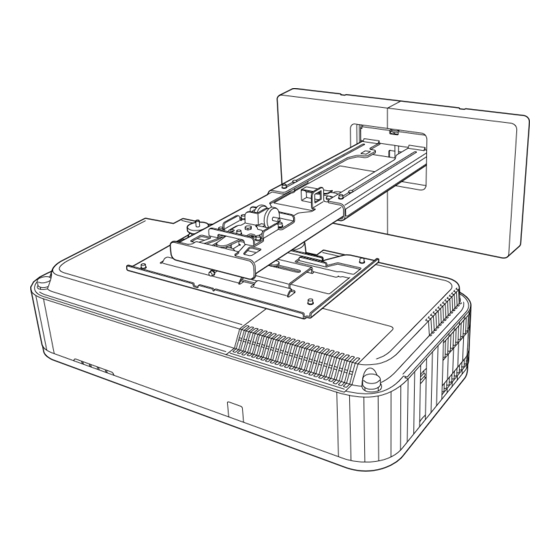
Installing the Setting Plate Attaching the Safety Wire Attach the carabiner and the safety wire to the bottom of the projector using the clamp... - Page 62 Installing the Setting Plate Place the projector into the arm unit and tighten the screws. Attach a carabiner to the hole in the arm section of the arm unit and pass the safety wire through it.
-
Page 63: Setting The Projector
• Setup by connecting the computer and projector with a USB cable. • Make settings using Epson Projector Management. This guide explains the USB flash drive and the USB cable methods. For details on making settings using Epson Projector Management, see the Epson Projector Management Operation Guide. •... -
Page 64: Copying Saved Settings To Other Projectors
Setting the Projector Connect the USB flash drive to the projector's USB-A port • Connect the USB flash drive directly to the projector. If the USB flash drive is connected to the projector through a USB hub, the settings may not be saved correctly. •... -
Page 65: Setup By Connecting The Computer And Projector With A Usb Cable
Setting the Projector While holding down the [Menu] button on the remote control or the control panel, connect the power cord to the projector The Power indicator and the Status indicator turn blue, and the Laser indicator and the Temp indicator turn orange. -
Page 66: Copying Saved Settings To Other Projectors
Setting the Projector While holding down the [Esc] button on the remote control or the control panel, connect the power cord to the projector The Power indicator and the Status indicator turn blue, and the Laser indicator and the Temp indicator turn orange. -
Page 67: When Setup Fails
Writing the settings may have failed and an error may have occurred blue, and the Laser and the Temp indica- in the projector's firmware. Stop using the projector, remove the tors flashing orange quickly? power plug from the electrical outlet, and contact Epson for help. -
Page 68: Side
Setting the Projector Installing Multiple Projectors Side-by-Side You can project the same image from multiple projectors. There are two ways to link multiple projectors together; as a daisy-chain or by using a distributor connection. You can connect up to four projectors in a daisy-chain formation. Make connections and the necessary settings in the following order. - Page 69 Setting the Projector Select Projector ID from the Multi-Projection menu Select the ID number for the projector Press the [Esc] button to close the menu Repeat steps 1 to 4 for the remaining projectors. Point the remote control at the projector you want to operate, and then press the [ID] button The current ID number is displayed on the projection screen.
-
Page 70: Hdmi Link Settings
Setting the Projector While holding down the [ID] button, press the button with the same number as the projector ID for the projector you want to operate Remote control operations for the projector with the selected ID are enabled. • When Projector ID is set to Off, you can operate the projector using the remote control regardless of the ID setting selected using the remote control. - Page 71 Setting the Projector Set the HDMI Link as shown below. Setting First projector to con- Middle projector End projector nect to device HDMI Out Power Link On HDMI Out End This may not function correctly if there are five projectors or more in the daisy-chain or if the settings are incorrect.
-
Page 72: Appendix
Appendix List of Safety Symbols The following table lists the meaning of the safety symbols labeled on the equipment. Symbol mark Approved stand- Meaning ards IEC60417 Power On No.5007 To indicate connection to the mains. IEC60417 Power Off No.5008 To indicate disconnection from the mains. IEC60417 Standby No.5009... - Page 73 Appendix Symbol mark Approved stand- Meaning ards IEC60417 Alternating current No.5032 To indicate that the equipment is suitable for alternating current only; to identify relevant terminals. IEC60417 Direct current No.5031 To indicate that the equipment is suitable for direct current only; to identify relevant terminals.
- Page 74 Appendix Indication of the manufacturer and the importer in accordance with requirements of directive 2011/65/ EU (RoHS) Manufacturer: SEIKO EPSON CORPORATION Address: 3-5, Owa 3-chome, Suwa-shi, Nagano-ken 392-8502 Japan Telephone: 81-266-52-3131 http://www.epson.com/ Importer: SEIKO EUROPE B.V. Address: Azië building, Atlas ArenA, Hoogoorddreef 5, 1101 BA Amster-...
-
Page 75: General Notice
Microsoft and Windows are trademarks or registered trademarks of Microsoft Corporation in the United States and/or other countries. HDMI, the HDMI logo, and High-Definition Multimedia Interface are trademarks or registered trademarks of HDMI Licensing Administrator, Inc. © 2023 Seiko Epson Corporation...
Need help?
Do you have a question about the EB-810E and is the answer not in the manual?
Questions and answers