Table of Contents
Advertisement
Quick Links
INSTALLATION, COMMISSIONING & SERVICING INSTRUCTIONS
ECONOMAIRE 31/INTEJAN has been tested and certified by Advantica for use with NATURAL gas G20.
Note: These instructions have been written to service both the ECONOMAIRE 31 and the ECONOMAIRE 31/INTEJAN. If your
heater does not have the intejan circulator fitted, simply ignore the relevant section/s.
1
2
3
4
5
6
7
1.
1.1
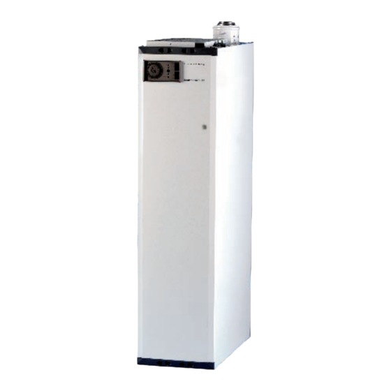
ECONOMAIRE 31/INTEJAN is a fan assisted downflow ducted warm air heater, which is fan flued and room sealed. The
heater is supplied with digital temperature control (for maximum comfort) and a water circulator as standard. In addition, a
rear rising duct kit is available for both models as well as an INTEJAN circulator kit for retro-fit to the ECONOMAIRE 31.
These instructions are to be left with the User or adjacent to the Gas Meter
ECONOMAIRE 31/INTEJAN
WARM AIR HEATER
Air Heater 42-416-16
Water Circulator 53-416-3b
ON
12
9
3
ON
IMPORTANT
max
o f f
Heater with Sealing Panel removed
BRIEF DESCRIPTION
G.C. Numbers:
19
18
17
16
15
6
14
13a
13
min
12
11
10
9
8
Fig. 1
1
Publication No. ZZ 1122/6
February 2008
1.
Thermista-stat
2.
Time control
3.
Air circulator fan
4.
Circuit diagram label
5.
Gas connection
6.
Circulator thermostat
7.
Gas cock
8.
Ignition burner
9.
Main burner assembly
10. Intejan circulator
11. Water return connection
12. Water flow connection
13. Air heater multifunction control
13a. Intejan multifunction control
(ECONOMAIRE 31 INTEJAN)
14. Flue gas test point
15. LED diagonstics indicator
16. Control module
17. Combustion air fan
18. Filter
19. Flue adapter
Fig.2
Sealing Panel
Advertisement
Table of Contents

Subscribe to Our Youtube Channel
Related Manuals for Johnson & Starley ECONOMAIRE 31


Summary of Contents for Johnson & Starley ECONOMAIRE 31
- Page 1 (for maximum comfort) and a water circulator as standard. In addition, a rear rising duct kit is available for both models as well as an INTEJAN circulator kit for retro-fit to the ECONOMAIRE 31.
-
Page 2: L O W R A Te
The air heater output can be adjusted between 7.3kW (26.4MJ/h, 25,000 Btu/h) and 8.8kW (31.7MJ/h, 30,000 Btu/h) “summer air circulation” of unheated air is available by manual selection (see the user’s instructions). INTEJAN output is 3.5kW (12.6MJ/h; 11,900Btu/h).). Installation shall be in accordance with the current editions of:- Building Standards (Scotland) (Consolidation) Regulations Building Regulations Gas Safety (Installation and Use) Regulations (as amended) -
Page 3: Return Air
HEATER COMPARTMENT AND CLEARANCES (See BS 5864) IMPORTANT: If the heater is to be fitted to an existing base duct (warm air plenum), always ensure that installation is carried out such that the rear left hand corner of the heater is aligned with the rear left hand corner of the base duct, so that any overhang or blanking off will be at the front and/or right hand side. - Page 4 INSTALLATION REQUIREMENTS NOTE: THIS APPLIANCE MUST ONLY BE INSTALLED WITH THE SUPPLIED ACCESSORIES AND TERMINAL. The ECONOMAIRE 31/INTEJAN can be used with horizontal or vertical flue types C12 and C32. You should FLUES also consult (or be familiar with) British Standards BS 5440 Pt. 1 Flues 5.1.1...
- Page 5 HORIZONTAL TERMINAL LOCATION: 5.2.1 The terminal must be positioned on the outside of the building and allow for the free passage of air across it at ALL times. 5.2.2 Avoid positions where the terminal is adjacent to projections, particularly under a balcony or immediately adjacent to a drain pipe.
- Page 6 Horizontal Flue Terminal (Showing Maximum Protrusion) VERTICAL TERMINAL LOCATION: 5.3.1 The ECONOMAIRE 31/INTEJAN is designed to be used with a vertical flue where the installation of a horizontal flue is either not possible or not desired. 5.3.2 Installation of a vertical flue can be achieved on either a flat or pitched roof with a pitch angle of between 25 5.3.3...
- Page 7 ° 0 e t i ° 5 e t i e t i e t i c i t e t i c i t a t t e t i r a l a t t r a l t a l z i r l a t...
-
Page 8: Air Heater Commissioning
iii. Where it will be affected by warm air ducts, diffusers, waste pipes or the heater itself. Where it will be subjected to vibration. Connect the thermista-stat wires to terminals ‘8’ and ‘9’ on the terminal block (see Figs. 13 & 14). GAS (See BS 5864 and BS 6891) 5.5.1 The local gas supply conditions MUST be adequate for the specified burner pressures as stated in the technical... -
Page 9: Safety Check
Time control Terminal block Cover plate screws Indicator panel LED status indicator Fig. 7 Electrical Door Assembly (showing time control, indicator panel and status indicator) 6.3.13 Allow the air heater to operate for a minimum of 15 minutes to ensure stability. 6.3.14 Reset the thermista-stat to the desired comfort level 6.3.15 Set the time control to the desired “on and “off”... - Page 10 1. Inlet Pressure Test Point. 2. Outlet Pressure Test Point. 3. Burner Pressure Adjuster. Fig. 8 Multifunction Control mbar in.wg. 0.50 0.20 0.375 0.15 0.25 0.10 0.05 0.125 320 ft/min 0.11 0.12 0.14 0.13 0.15m/sec Air Volume Fan Performance Curve...
-
Page 11: Intejan Circulator
6.6.6 Allow the heater to run for a period of 5 minutes to stabalise. 6.6.7 Turn off gas supply to heater at the heater Gas Cock. DO NOT TURN OFF AT GAS METER! 6.6.8 Having detected the fault condition, the module should cause the red LED on the indicator panel to flash and the module will go through the ignition sequence. -
Page 12: Water Connections
WATER CONNECTIONS: Note: Both flow and return connections are Rp in BSP female) connections. IMPORTANT:Use compression fittings at the appliance flow and return connections and at the air heater casing exit, to facilitate easy access to the circulator body. 7.2.1 Remove the fixing screws holding the sealing panel in place. -
Page 13: Safety Checks
8.1.3 Refit the sealing panel and secure using the fixing screws. NOTE: Whilst the sealing panel needs to be fixed in such a manner so as to ensure an air tight seal, care MUST be taken not to over tighten the fixing screws. LIGHTING IGNITION AND MAIN BURNERS: 8.2.1 Turn on the gas supply to the heater. -
Page 14: Routine Maintenance
8.4.9 Reinstate gas supply and wait for a minimum period of 10 seconds. 8.4.10 Depress the “RESET” button on the indicator panel. 8.4.11 The heater will go through its ignition procedure and the ignition and main burners SHOULD ignite. 8.4.12 Set the “WATER HEATER” switch on the time control unit to “TIMED” INSTRUCTIONS FOR USERS If the building is unoccupied, ensure that the user instructions are left taped to the air heater for the the user’s reference and that the installation instructions are left at or near the air heater for use on future service calls. - Page 15 10.1.12 Locate the flue gas test point (see fig.1) and attach a flue gas analyser to the test point in accordance with the manufacturer’s instructions. NOTE: the CO/CO ratio should be no greater than 0.008 10.1.13 Fully commission the appliance in accordance with paragraphs 6 and 8. NOTE:The flue gas test MUST NOT be used as an alternative to servicing the heater! 10.2 MULTIFUNCTION CONTROL AND AIR HEATER/WATER CIRCULATOR BURNER ASSEMBLY REMOVAL:...
-
Page 16: Control Module Removal
10.6 AIR CIRCULATING FAN, REMOVAL AND CLEANING: 10.6.1 Ensure that the electrical supply is isolated. 10.6..2 Remove the front door from the heater and remove the 3 x fixing screws on the electrical door assembly. 10.6.3 Open the door assembly outwards on its hinges (see fig. 7) such that access is gained to the rear of the assembly. 10.6.4 Disconnect the fan flying leads from the fan assembly. - Page 17 Time Control removal: 10.8.3 Disconnect spade terminal connectors “C1”, “C2”, “C3” and “C5” from the time control. 10.8.4 Release the 3 x fixing screws securing the clock mounting plate to the electrical door and withdraw the total assem- bly from the door. 10.8.5 Remove the 3 X M3 bolts that secure the time clock mechanism and remove from the mounting plate.
-
Page 18: Defect Diagnosis
10.11. FLUE FAN, REMOVAL AND CLEANING 10.11.1 Remove the air circulation fan as detailed at 10.6 10.11.2 Disconnect the power supply to the pressure swich. 10.11.3 Carefully remove the feed pipes to the pressure switch TAKING CARE TO NOTE THEIR POSITION. 10.11.4 Unscrew the 2 x fixing screws holding the pressure switch in place and remove the switch. - Page 19 START Water circulator Air heater Timed or continuous operation Thermostat Thermista-stat Demand Demand for water for air heat heat Module powers up RESET RESET Is no-flow LOCKOUT LOCKOUT provided? Fan starts Pressure switch operates Is flow provided? Thermostat Thermista-stat Demand Demand for water for air...
- Page 22 Fig.13 ECONOMAIRE 31 Flow Diagram...
- Page 23 Fig. 15 Schematic Diagram (showing connection of an external controller)
- Page 24 Fig. 17 Exploded Diagram...
-
Page 25: Front View
KNOCKOUTS FOR WATER CONNECTION (BOTH SIDES) KNOCKOUTS FOR GAS CONNECTION KNOCKOUTS FOR WATER CONNECTION (BOTH SIDES) 546 NOM FRONT VIEW SIDE VIEW WATER ENTRY/EXIT (RETURN) WATER ENTRY/EXIT (FLOW) ELECTRICAL ENTRY BASE VIEW PLAN VIEW Fig. 16 ECONOMAIRE 31 - Principal Dimensions... - Page 26 Fig.14 ECONOMAIRE 31 Logic Diagram...
- Page 27 LIST OF SPARES (See Fig.17) ECONOMAIRE 31 and ECONOMAIRE 31/INTEJAN Item G.C. No Part No Description E69625 1000-0521020 Wiring harness E80119 1000-0521860 Wiring harness (air heater) N310-0350005 Heat exchanger N312-0350005 Heat exchanger (from serial no. 59000501) E80123 1000-0521820 FDC & limit switch...
- Page 28 Johnson and Starley prides itself on its ability to supply spare parts quickly and efficiently. If you have a problem in obtaining a spare part, please contact our Spares Department at the address below. JOHNSON & STARLEY LTD. Telephone: (01604) 762881 Rhosili Road, Brackmills, Fax:...
Need help?
Do you have a question about the ECONOMAIRE 31 and is the answer not in the manual?
Questions and answers