Table of Contents
Advertisement
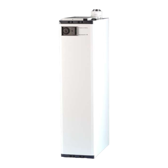
ECONOMAIRE 32
WARM AIR HEATER
Intejan Water Circulator
with
INSTALLATION, COMMISSIONING &
SERVICING INSTRUCTIONS
G.C. NUMBERS: Air Heater
These instructions are to be left with the User or
adjacent to the Gas Meter
www.johnsonandstarley.co.uk
Johnson & Starley
42-416-14
Water Circulator
53-416-31
R E L I A B I L I T Y Y O U C A N T R U S T
Publication No. ZZ 1088-12
April 2010
Advertisement
Table of Contents

Related Manuals for Johnson & Starley ECONOMAIRE 32


Summary of Contents for Johnson & Starley ECONOMAIRE 32
- Page 1 Publication No. ZZ 1088-12 ECONOMAIRE 32 April 2010 WARM AIR HEATER Intejan Water Circulator with INSTALLATION, COMMISSIONING & SERVICING INSTRUCTIONS G.C. NUMBERS: Air Heater 42-416-14 Water Circulator 53-416-31 These instructions are to be left with the User or adjacent to the Gas Meter www.johnsonandstarley.co.uk...
-
Page 2: Table Of Contents
CONTENTS The Benchmark Scheme Features Brief Description Important Information Technical Data Heater Compartment & Clearances Ventilation Air Duct System Flue Instructions Electrical Gas Air Heater Commissioning Intejan Circulator Intejan Circulator Commissioning Users Instructions Maintenance Defect Diagnosis Diagnosis Flow Charts Logic Diagram Schematic Diagram Circuit Diagram Dimensions List of Spares Exploded Diagram Economaire Ancillaries Benchmark Checklist THE BENCHMARK SCHEME In order to comply with Building Regulations Part L (Part J in Scotland) the boiler MUST be fitted in accordance with the manufacturer’s instructions. -
Page 3: Features
(for maximum comfort) and a water circulator as standard. In addition, a rear rising duct kit is available for both models as well as an INTEJAN circulator kit for retro-fit to the ECONOMAIRE 32. -
Page 4: Important Information
(i.e. GAS SAFE REGISTERED INSTALLERS. GAS SAFE MEMBERSHIP ENQUIRIES - TEL: 0800 408 5500) IN ACCORDANCE WITH THE GAS SAFETY (INSTALLATION AND USE) REGULATIONS (CURRENT EDITION). FAILURE TO COMPLY WITH THESE REGULATIONS MAY LEAD TO PROSECUTION. 4. TECHNICAL DATA ECONOMAIRE 32 INTEJAN ECONOMAIRE 32 WATER CIRCULATOR WEIGHT... -
Page 5: Ventilation Air
In under-stairs installations, the compartment must comply with the relevant section of BS 5864, provided that in addition all internal surfaces (including the base) are non-combustible or lined with non-combustible material. This requirement is applicable only to dwellings of more than two storeys. In free-standing installations, (see instructions packed with TC32 or TC32R top closure kit), only one or two walls will be in close proximity to the air heater;... -
Page 6: Flue Instructions
INSTALLED WITH A SLIGHT FALL AWAY FROM THE HEATER. VERTICAL TERMINAL LOCATION 8.3.1 The ECONOMAIRE 32/INTEJAN is designed to be used with a vertical flue where the installation of a horizontal flue is either not possible or not desired. 8.3.2 Installation of a vertical flue can be on either a flat or pitched roof with a pitch angle of between 25˚ and 50˚. - Page 7 FIGURE 3 TERMINAL POSITIONS TABLE 7 TERMINAL POSITION MINIMUM DISTANCE Directly below an opening, air brick, opening window etc 300mm Above an opening, air brick, opening window, etc. 300mm Horizontally to an opening, air brick, opening window etc. 300mm Below gutters, soil pipes or drain pipes. 75mm Below eaves.
- Page 8 FIGURE 4 HORIZONTAL FLUE OUTLET PROTRUSION FIGURE 5 PLUME TERMINAL OUTLET DIMENSIONS ITEM DESCRIPTION PART No. COLOUR 90˚ Standard Flue Elbow 1000-0014840 White 45˚ Flue Elbow 1000-0014850 White 500mm Extension 1000-0014870 White 1000mm Extension 1000-0014860 White Vertical Terminal & Support Bracket 1000-0014880 Anthracite Vertical Terminal &...
-
Page 9: Electrical
ELECTRICAL WARNING: THIS APPLIANCE MUST BE EARTHED! MAINS 9.1.1 The heater is supplied with mains cable (PVC sheathed, heat resisting to 85˚C), 3 core: Brown; Blue; Green/Yellow, 6A, 0.75mm²), connected to a terminal block and exiting through the heater at the right hand top. The cable is suitable for a 230V 50Hz supply and requires connection to the fixed wiring using a double pole switched, fused spur with a contact separation of at least 3mm in ALL poles. - Page 10 11.3.4 Locate the status LED indicator which can be TIME CONTROL INDICATOR PANEL observed through the inspection hole in the bottom right hand corner of the control module. TERMINAL BLOCK 11.3.5 Turn on the mains power supply to the heater 11.3.6 Set the “AIR HEATER”...
- Page 11 11.4 MAIN BURNER PRESSURE TEST NOTE: AIR HEATER BURNERS ARE FACTORY SET TO PROVIDE A NOMINAL HIGH RATE OUTPUT AS DETAILED IN TABLE 4 11.4.1 Loosen the screw on the outlet pressure test point and fit a pressure test gauge (see Figure 7) 11.4.2 Check the gauge reading against the information at Table 4.
-
Page 12: Intejan Circulator
12. INTEJAN CIRCULATOR 12.1 WATER CIRCULATION SYSTEM Detailed recommendations for the water circulation system are given in BS 6798, BS 5449 (for small bore and microbore central heating systems), and BS 5446. The maximum water side operating pressure (PMS) is 1bar. 12.1.1 To ensure good circulation in gravity circuits, flow pipes should be designed to run vertically from the water heater... -
Page 13: Intejan Circulator Commissioning
INTEJAN CIRCULATOR COMMISSIONING 13.1 PREPARATION 13.1.1 Ensure that the gas and electrical supplies are OFF. 13.1.2 Fill the water circulation system, clear any air locks and check for water soundness, sealing any leaks detected. 13.1.3 Refit the sealing panel and secure using the 15 x fixing screws. NOTE: Whilst the sealing panel needs to be fixed in such a manner so as to ensure an air tight seal, care MUST be taken not to over tighten the fixing screws. -
Page 14: Users Instructions
13.3 WATER BURNER PRESSURE TEST NOTE: THE WATER CIRCULATOR BURNERS ARE PRE-SET AND SHOULD NOT REQUIRE ADJUSTING. 13.3.1 Loosen the screw on the outlet pressure test point and fit a pressure test gauge (see Figure 7) 13.3.2 Check the gauge reading against the information at Table 4. 13.3.3 If necessary, use the burner pressure adjuster to obtain the required gauge reading as shown at Table 4. - Page 15 15.1.7 Clean the heat exchanger flueways by thoroughly brushing from above and below. 15.1.8 By viewing through the fan aperture, and using a torch or similar, examine the heat exchanger externally for signs of cracks or holes, particularly around welded joints. 15.1.9 Using a torch or similar, introduce a light source into the heat exchanger burner aperture and upper access port, and again examine the heat exchanger for signs of cracks or holes, particularly around welded joints,...
- Page 16 15.6.3 Open the door assembly outwards on its hinges (see Figure 7) such that access is gained to the rear of the assembly. 15.6.4 Disconnect the fan flying leads from the fan assembly. 15.6.5 Release the fan assembly securing screw and withdraw the fan assembly from the heater cabinet, avoiding damage to the fan blades.
- Page 17 15.8.15 Re-fitting of the electrical door assembly is in reverse order. 15.8.16 Close the electrical door assembly and secure using the 3 x fixing screws. 15.8.17 Set the time control to correct time. 15.8.18 Set the time control to the required “ON” and “OFF” periods. 15.9 FAN DELAY CONTROL/LIMIT SWITCH REMOVAL 15.9.1 Ensure that the electrical supply is isolated.
-
Page 18: Defect Diagnosis
DEFECT DIAGNOSIS IMPORTANT: If an electrical defect occurs after installation of the appliance; preliminary earth continuity, polarity, and resistance to earth checks should be carried out with a multimeter. On completion of any maintenance/fault-finding task that has required the breaking and remaking of electrical connections, then checks of continuity, polarity, and resistance to earth must be repeated. -
Page 19: Diagnosis Flowcharts
17. DIAGNOSIS FLOWCHARTS FIGURE 12 CONTROL FLOWCHART Telephone: 01604 762881... - Page 20 FIGURE 13 AIR HEATER DIAGNOSIS FLOWCHART www.johnsonandstarley.co.uk...
- Page 21 FIGURE 14 CONTROL FLOWCHART Telephone: 01604 762881...
-
Page 22: Logic Diagram
18. LOGIC DIAGRAM FIGURE 15 LOGIC DIAGRAM www.johnsonandstarley.co.uk... -
Page 23: Schematic Diagram
19. SCHEMATIC DIAGRAM FIGURE 16 SCHEMATIC DIAGRAM Telephone: 01604 762881... -
Page 24: Circuit Diagram
20. CIRCUIT DIAGRAM Showing connections of an external controller FIGURE 17 CIRCUIT DIAGRAM www.johnsonandstarley.co.uk... -
Page 25: Dimensions
21. DIMENSIONS FIGURE 18 DIMENSIONS Telephone: 01604 762881... -
Page 26: List Of Spares
LIST OF SPARES 01604 707012 Telephone Johnson & Starley Spares Department ITEM G.C. No. PART No. DESCRIPTION E69625 1000-0521020 Wiring Harness E80119 N320-0350005 Wiring Harness (air heater) Heat Exchanger N322-0350005 Heat Exchanger (from serial number 54000501) E69627 1000-0520990 FDC & Limit Switch 1000-0522340 FDC & Limit Switch (from serial number 54000501) E69623 N320-0145000 Filter Assembly... -
Page 27: Exploded Diagram
EXPLODED DIAGRAM FIGURE 19 EXPLODED DIAGRAM Telephone: 01604 762881... -
Page 28: Economaire Ancillaries
British Standard BS 5864 and the Heating Compliance Guide For further information contact Johnson & Starley on Telephone: 01604 762881 These kits are readily available from Johnson & Starley Ltd Telephone the Sales Office for further information ECONOMAIRE 32 ANCILLARY’S Description Product Code Cleanflow Air Filter ECF32 Return Air Plenums RAP32 Side Return Air Kits... - Page 29 ECONOMAIRE 32 LOG BOOK WARM AIR HEATER AND WATER CIRCULATOR COMMISSIONING CHECKLIST This Log Book should be filled out at each annual service Telephone: 01604 762881...
-
Page 30: Benchmark Checklist
WARM AIR HEATER AND CIRCULATOR COMMISSIONING CHECKLIST This Commissioning Checklist is to be completed in full by the competent person who commissioned the warm air unit and associated equipment as a means of demonstrating compliance with the appropriate Building Regulations and then handed to the customer to keep for future reference. Failure to install and commission this equipment to the manufacturer’s instructions may invalidate the warranty but does not affect statutory rights. - Page 32 Johnson & Starley are the leading UK & European manufacturers of a complete range of Domestic Warm Air Heaters. All the heaters suit both Replacement and Upgrade needs and are compliant with the new (2006) amendments to Part L of the Building Regulations. HOME COMFORT SOLUTIONS Company Details Website Address...
Need help?
Do you have a question about the ECONOMAIRE 32 and is the answer not in the manual?
Questions and answers