Table of Contents
Advertisement
Advertisement
Table of Contents

Related Manuals for Johnson & Starley WARMCAIR C36U


Summary of Contents for Johnson & Starley WARMCAIR C36U
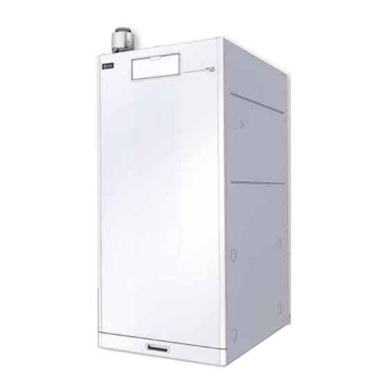
- Page 1 Publication No. ZZ 1414-4 December 2016 WARMCAIR C36U Condensing Air Heater High Efficiency Upflow Condensing Air Heater INSTALLATION, COMMISSIONING & SERVICING INSTRUCTIONS WarmCair C36U G.C. No. 42-451-27 These instructions are to be left with the User www.johnsonandstarley.co.uk...
-
Page 2: Table Of Contents
CONTENTS The Benchmark Scheme 15 Handing Over Features 16 Servicing & Maintenance Servicing Schedule General Description Servicing Sequence Component Servicing Checklist Building Standards & Regulations Gaining Access for Servicing Main Burner Assembly Safety &Gas Information Ignition & Flame Detection Electrode General Safety Information Heat Exchanger/Combustion Chamber Gas Categories... -
Page 3: Features
It is room sealed, with a stainless steel heat exchanger, using a vertical or horizontal Concentric Flue System. The WarmCair C36U air heater is ideally suited for new built dwellings and the replacement of existing non- condensing air heaters. -
Page 4: Building Standards & Regulations
BUILDING STANDARDS & REGULATIONS STATUTE LAW DEFINES THAT ALL GAS APPLIANCES MUST BE INSTALLED BY COMPETENT PERSONS, i.e. GAS SAFE REGISTERED INSTALLERS. GAS SAFE MEMBERSHIP ENQUIRIES TEL: 0800 408 5500 IN ACCORDANCE WITH THE GAS SAFETY (INSTALLATION AND USE) REGULATIONS (CURRENT EDITION). FAILURE TO COMPLY WITH THESE REGULATIONS MAY LEAD TO PROSECUTION. -
Page 5: Safety &Gas Information
SAFETY & GAS INFORMATION PLEASE READ THESE INSTRUCTIONS CAREFULLY BEFORE COMMENCING WITH THE INSTALLATION GENERAL SAFETY INFORMATION 4.1.1 Ensure the mains supply voltage, frequency, number of phases and power rating comply with details on the rating label. 4.1.2 All wiring must be in accordance with the appropriate standards. The equipment must be supplied with a double pole isolator switch. -
Page 6: Heater Positioning
HEATER POSITIONING This heater is not suitable for external installation unless it is protected from the elements by a suitable enclosure. The enclosure must provide the clearance for installation, servicing and maintenance as well as the correct level of ventilation. The selected position should allow for a suitable flue system to be installed. When installed in a timber frame building guidance should be taken from the Gas Industry Publication IGE/ UP-7 (Guide for Gas Installations in Timber Frame Housing). -
Page 7: Duct System
DUCT SYSTEM (See British Design Manual - Gas fired Warm Air Heating) RETURN AIR 8.1.1 Room-sealed appliances may be installed without return air ducting, provided that the path between the return air grille and the appliance return air inlet is protected in such a manner that the required air-flow will be maintained at all times. -
Page 8: Flue Instructions
FLUE INSTRUCTIONS The WarmCair C36U Condensing Air Heater is certified as a warm air heater with corresponding flue systems according to EU Directive 2009/142/EC on gas-fired devices. These installation instructions are covered by this certification and are referred to in the design approval test certificate. - Page 9 FIGURE 5. TERMINAL POSITIONS TERMINAL POSITION MINIMUM DISTANCE Directly below an opening, air brick, opening window etc 300mm Above an opening, air brick, opening window, etc. 300mm Horizontally to an opening, air brick, opening window etc. 300mm Below gutters, soil pipes or drain pipes. 75mm Below eaves.
-
Page 10: Types Of Flue Systems
FLUE REQUIREMENTS & GENERAL INFORMATION 9.8.1 Extended horizontal and vertical concentric flues (80/125mm diameter) with balanced terminals may be WarmCair C36U warm air heater installed on the 9.8.2 If an extended horizontal flue is being used it must have a continuous fall back towards the appliance of 3°... - Page 11 CONVENTIONAL 80/125mm FLUE ACCESSORY PARTS No’s DESCRIPTION COLOUR APPLICATION PART No. 800mm Horizontal Terminal White Horizontal 1000-0023830 Vertical Adaptor 60mm to 80mm White Vertical 1000-0023810 45° Elbow White Horizontal & Vertical 1000-0020110 90° Elbow White Horizontal & Vertical 1000-0020100 500mm Straight Extension White Horizontal &...
-
Page 12: Extended Horizontal Flue System
9.12 EXTENDED HORIZONTAL FLUE SYSTEM CLAMP Extended horizontal flue set up comprises of: 90° ELBOW The required flue lengths up to a length of 10m 80/125mm Horizontal Terminal Kit HORIZONTAL 90° Elbow TERMINAL 60/100mm to 80/125mm Adapter EXTENSION Inside Wall Cover Plate LENGTH ADAPTER Outside Wall Cover Plate... -
Page 13: Condensate Pump & Drain Tube
CONDENSATE PUMP & DRAIN TUBE 10.1 CONDENSATE PUMP 10.1.1 Supplied with 6mm x 10m condense tube. Condense adapter and 2 x clips SAFETY NOTE: If the pump fails, the safety float switch will shut off the heater operation. 10.1.2 DO NOT HANDLE PUMP IN WET CONDITIONS OR WITH WET HANDS. 10.1.3 To reduce the risk of electric shock, ensure the electrical supply is permanently wired to earth 10.1.4 TECHNICAL DATA Tank capacity : 0.7L... -
Page 14: Electrical
GAS (See BS 5864 and BS 6891) 11.1 The local gas supply conditions MUST be adequate for the specified burner pressures as stated in the technical specification (section 5). 11.2 An independent gas supply pipe from the meter is to be preferred wherever possible. Where this is not possible, the pipe must be capable of taking the complete input of the heater and all other gas appliances being served by the same pipe. -
Page 15: Time Control
FITTING INSTRUCTIONS CAUTION: This appliance exceeds the recommended weight for a one man lift as detailed in the Manual Handling Operations, 1992 Regulations. It should be noted that this appliance could contain sharp edges and care MUST be taken when handling. 13.1 FITTING THE APPLIANCE 13.1.1... -
Page 16: Gas Rate Check
If the system includes ceiling diffusers, the air through these should be NOT LESS THAN 1.5m/s (300ft/ NOTE: min), except for very small rooms, (i.e. bathrooms etc.). Outlet faces may require partial blanking in order to achieve this. 14.5 LIGHTING MAIN BURNER 14.5.1 Turn on the gas supply to the heater. -
Page 17: Handing Over
HANDING OVER 15.1 After commissioning, the installer should hand the appliance over to the occupier of the house by the following procedure: 15.2 Hand the User Instructions ZZ1340 to the occupier and explain their responsibilities in respect of current legislation and regulations, both national and local. 15.3 Explain and demonstrate how to light and shut down the appliance. -
Page 18: Servicing & Maintenance
SERVICING & MAINTENANCE 16.1 SERVICING SCHEDULE To ensure that the appliance gives continued operation that is both safe and efficient, it is necessary to carry out regular service checks and whilst the period between servicing will depend on the installation condition and the demands placed upon the appliance, it is recommended that the appliance be serviced annually. -
Page 19: Gaining Access For Servicing
16.3 GAINING ACCESS FOR SERVICING 16.3.1 Ensure the electrical & gas supply is isolated as needed. 16.3.2 Remove the return air filter. 16.3.3 Remove the front panel by unscrewing the 4 retaining screws at top and bottom of the panel. 16.3.4 Remove the front cover. -
Page 20: Sliding Flue Connector
16.6 HEAT EXCHANGER/COMBUSTION CHAMBER 16.6.1 Refer to section 16.3, 16.4 and Figure 18. 16.6.2 Once the burner assembly has been removed inspect the inside of the combustion chamber for debris. If the inner insulation is damaged, do NOT try to clean. Replace the heat exchanger. 16.6.3 Refit in reverse order. -
Page 21: Condensate Trap
FLUE COLLECTION TRAY CONDENSE PIPE FLUE CONDENSE OUTLET FROM PIPE OUTLET COMBUSTION TRAY FROM TO PUMP COMBUSTION AIR FAN CONDENSE DRAIN TUBE MUST HAVE A 6mm FALL CONDENSING DRAIN PIPE FROM COMBUSTION AIR FAN TO CONDENSATE TRAP CONDENSATE TRAP CONDENSATE PIPE FROM CONDENSATE COMBUSTION TRAY... -
Page 22: Return Air Filter
REPLACEMENT PARTS 17.1 IMPORTANT: Before commencing with any part replacement the appliance should be isolated from the electrical supply and the gas service cock on the appliance closed. P1 AIR 17.1.1 All parts removed should be replaced and refitted in reverse PRESSURE TUBE FLYING LEAD order, ensuring correct seals are made and wires are connected... -
Page 23: Esys
17.8 CONDENSATE DRAIN PUMP CONDENSE PIPE 17.8.1 Refer to section 16.3. CONNECTIONS FROM THE COMBUSTION 17.8.2 Remove the wires from the terminal strip marked fan compartment TRAY for the float switch condensate pump. CONDENSE 17.8.3 Disconnect the condensate pipes from the pump. Taking care DRAIN as these will contain water. -
Page 24: Burner Assembly
17.11 BURNER ASSEMBLY 17.11.1 Refer to section 16.3. 17.11.2 Unscrew the gas joint at the top of the gas cock. 17.11.3 Remove the ESYS (red ignition box) & gas valve venturi assembly. Refer to 17.10 & 17.9 and Figure 25. 17.11.4 Remove the 4 nuts which secure the burner assembly. -
Page 25: Control Panel Modes
18. CONTROL PANEL MODES FIGURE 30. CONTROL PANEL CONTROL PANEL Time control LED Display Summer Air Circulation Reset 18.1 TEST MODE 18.1.1 To put the appliance in test mode, press Summer Air Circulation (SAC) and C buttons together for more than 3 seconds, until the display changes. (Possible 5 second time delay.) 100 is displayed along with the flame symbol. - Page 26 FAULT CODE TABLE 19.1 CAUTION Before commencing any mechanical servicing the appliance should be isolated from the electrical supply and the gas service cock on the appliance closed. All parts that are removed during a service operation should be replaced in reverse order, ensuring correct seals are made and wires are connected correctly. During the service remove any debris from within the appliance.
- Page 27 BLOCKING CODES CODE SYMPTOM POSSIBLE CAUSE ACTION Check wiring and connections for shorting to earth Duct air temperature sensor short Temperature sensor shorted to earth circuit or failed Check sensor resistance Check wiring connections Duct air temperature sensor open Temperature sensor not connected circuit or failed Check sensor continuity...
-
Page 28: Fault Finding Flowcharts
FAULT FINDING FLOW CHART www.johnsonandstarley.co.uk... -
Page 29: Defect Diagnosis For The Circulation Air Fan
DEFECT DIAGNOSIS FOR THE CIRCULATION AIR FAN 21.1 CIRCULATION AIR FAN 21.1.1 Ensure Air Circulation Fan is running at maximum. 21.1.2 A voltage should be measured and blue (-) and yellow (+). Voltage approx. 10 VDC. 21.1.3 If voltage is present and fan is not running at maximum. Replace ACF. Sales/Spares &... -
Page 30: Gas Valve
FUNCTIONAL WIRING DIAGRAMS DSP (MMI) CONDENSATE PUMP GNYE CONTROL PANEL TIMER 1 2 3 4 COLOUR BLACK PCB INTERFACE BLUE GREEN BROWN GNYE OPENTHERM FLOAT SWITCH PCB - INTERFACE PCB - INTERFACE PCB - INTERFACE UNIT GNYE GREEN/YELLOW AMBIENT GREY ROOM SENSOR BK BK... - Page 31 FIGURE 32. WIRING DIAGRAM No. 2 WIRING ROUTING TABLE FROM UNIT WIRE COLOUR TERMINAL L/N/E TO UNIT TERMINAL FROM UNIT WIRE COLOUR TERMINAL L/N/E TO UNIT TERMINAL white A1 - 2 ESYS X3 - 1 blue X9 - 2 PCB INTERFACE black A1 - 3 ESYS...
-
Page 32: Dimensions
DIMENSIONS SIDE VIEW FRONT VIEW TOP VIEW BASE VIEW FIGURE 33. C36U DIMENSIONS www.johnsonandstarley.co.uk... - Page 33 EXPLODED SPARES DIAGRAMS ITEM DESCRIPTION PART No. G. C. No. C10D-0501005 CONTROL PANEL ASSEMBLY FLANGE CONNECTION COMBUSTION AIR FAN (CAF) ASSEMBLY 1000-0525215 J24-837 Includes 3 & 4 CAF GASKET SEALING RING 1000-1507860 H36-837 CAF ‘O’ RING 1000-2501670 J24-909 EXHAUST FLUE ELBOW ASSEMBLY 1000-0022195 J24-836 Includes 6 &...
- Page 34 ITEM DESCRIPTION PART No. G. C. No. FLYING LEAD C46U-0503005 AIR CIRCULATION FAN ASSEMBLY RETURN AIR SENSOR DUCT TEMPERATURE SENSOR 1000-0522645 J24-833 FLUE GAS SENSOR SEALING CONDENSATE FRAME AIR BOX SEAL COMBUSTION AIR BOX ASSEMBLY C46D-0139005 J24-829 Includes 19 & 20 SEALING RING 1000-2501680 J24-825...
- Page 35 ITEM DESCRIPTION PART No. G. C. No. ESYS CONTROL BOX 1000-0526595 J24-859 ESYS SCREW 1000-3004035 J24-855 ESYS COVER 1000-0522610 J24-856 AIR PRESSURE SWITCH 1000-0530135 J24-839 CONDENSATE TRAP 1000-0024525 J24-749 VERTICAL FLUE ADAPTER 60/100mm 1000-0022225 J24-784 TELESCOPIC FLUE 1000-00222525 J24-811 OPEN THERM SWITCH 1000-0525305 Sales/Spares &...
- Page 36 LIST OF ANCILLARIES WARMCAIR C36U ANCILLARY’S Description Product Code CF36 CLEANFLOW AIR FILTER A0212X0212 FILTER REPLACEMENT PADS (PACK OF 6) Side Return Air Kit Includes 4 SRAK36 BLANKING PLATE PASSIVE SIDE RETURN AIR KIT SRAK36P BASE DUCT WB36 www.johnsonandstarley.co.uk...
-
Page 37: Code Of Practice
Code Of Practice For the installation, commissioning and servicing of domestic heating and hot water products Benchmark places responsibilities on Standards of Work both manufacturers and installers.* • Be competent and qualified to undertake the work required. The purpose is to ensure that •... -
Page 38: Benchmark Checklist And Service Record
CONDENSING WARM AIR HEATING AND WATER HEATING COMMISSIONING CHECKLIST This Commissioning Checklist is to be completed in full by the competent person who commissioned the wsnn air unit and associated equipment as a means of demonstrating compliance with the appropriate Building Regulations and then handed to the customer to keep for future reference Failure to Install and commission this equipment to the manufacturer's instructions may Invalidate the warranty but does not affect statutory rights. -
Page 39: Service Record
SERVICE RECORD It is recommended that your heating system is serviced regularly and that the appropriate Service Interval Record is completed. Service Provider Before completing the appropriate Service Record below, please ensure you have carried out the service as described in the manufacturer’s instructions. SERVICE 01 SERVICE 02 Date:... - Page 40 Johnson & Starley Ltd Rhosili Road, Brackmills, Northampton NN4 7LZ sales@johnsonandstarley.co.uk marketing@johnsonandstarley.co.uk Reception/Customer Service 01604 762881 01604 767408 Anniversary 1922 - 2012...
Need help?
Do you have a question about the WARMCAIR C36U and is the answer not in the manual?
Questions and answers