
Related Manuals for Nanni Z4.205


Summary of Contents for Nanni Z4.205
- Page 1 NANNI MARINE ENGINE OPERATOR MANUAL DGBXXT09009A ENGINE T4.205 T4.230 T4.270 Z4.205 Z4.230 Z4.270...
-
Page 3: Q00 Tracked Changes
TRACKED CHANGES TRACKED CHANGES CODE INDEX DATE INITIALS NATURE OF TRANSLATIONS PAGES DGBXXT09009 12/2018 Create DGBXXT09009A 03/2021 EPA Certificate Please note all changes and pages associated. For further clarity, please add a line in front of each change. -
Page 5: Table Of Contents
SUMMARY Table des matières TRACKED CHANGES MICRO-ORGANISMS IN FUEL TRACKED CHANGES INERT IMPURITIES IN FUEL SUMMARY DIESEL LUBRICANTS INTRODUCTION PRECAUTIONS TO UNDERTAKE INTRODUCTION OILS RECOMMENDED OR AUTHORIZED ABOUT THIS MANUAL GENERALITIES CONTENT & UPDATES OILS VISCOSITY S02 SAFETY CORRESPONDENCE BETWEEN API AND ACEA OILS SUMMARY SAFETY SIGNALS DIESEL SULPHUR CONTENT... - Page 6 WATER LEVEL INDICATOR CHANGING THE OIL FILTER TRIM INDICATOR COOLING SYSTEM RUDDER INDICATOR OVERVIEW ELECTRONIC INSTRUMENTS COOLANT NANNI CONTROL PANELS COOLANT LEVEL COMPONENTS DRAINING THE COOLANT CIRCUIT SUMMARY COOLANT - FILLING ENGINE MAIN COMPONENTS RAW WATER SYSTEM STARTING & RUNNING...
- Page 7 If there are any equipment details that are not shown or described in this Manual, or if you have any question regarding the operation of any equipment, your authorized Nanni dealer will be glad to inform you of correct care and operating procedures.
-
Page 8: S01 Introduction
Please ensure that this Manual is always kept in the authorized Nanni Dealer will be glad to inform you of boat. It should always be available to anyone else using correct care and operating procedures. -
Page 9: S02 Safety
SAFETY SUMMARY SAFETY SUMMARY SAFETY SIGNALS SAFETY INFORMATION REPLACEMENT OF MISSING OR DAMAGED SAFETY SIGNS READ SAFETY INSTRUCTIONS ENGINE-GENSET SAFETY ICONS SAFETY PRECAUTIONS HOT EXHAUST PRECAUTIONS WORK IN VENTILATED AREA WASTE DISPOSAL UNWANTED ENGINE START SAFE MAINTENANCE PRACTICE WORK IN CLEAN AREA PROTECTIVE CLOTHING SERVICE ENGINES SAFELY PROPER USE OF TOOLS... -
Page 10: Safety Signals
Carefully read all safety messages in this manual and on If you do not understand any part your genset safety signs. of this document and need assistance, contact your Nanni Keep safety signs in good condition. Be sure new representative. equipment components and repair parts include the current safety signs. -
Page 11: Engine-Genset Safety Icons
SAFETY ENGINE-GENSET SAFETY ICONS Indicates the oil drain orifice. Some stickers are fixed directly on the engine. They are intended to help you to quickly identify the location of certain components and avoid possible hazards when working on the engine. Ensure that these stickers are always visible and replace them if torn or washed up. -
Page 12: Safety Precautions
SAFETY SAFETY PRECAUTIONS UNWANTED ENGINE START Avoid possible injury or death from engine runaway. Do not start engine by shorting HOT EXHAUST PRECAUTIONS across starter motor solenoid terminals posts. Engine will start if normal Servicing machine or attachments with circuitry is bypassed. Start engine from engine running can result in serious operator’s seat. -
Page 13: Service Engines Safely
SAFETY SERVICE ENGINES SAFELY PROPER LIFTING EQUIPMENT Tie long hair behind your head. Do not wear a necktie, scarf, loose clothing, or necklace when you work near moving parts. If these items were to get caught, severe injury could result. Remove rings Lifting heavy components incorrectly can cause severe and other jewelry to prevent electrical injury or equipment damage. -
Page 14: Staying Clear Of Rotating Drive Lines
SAFETY STAYING CLEAR OF ROTATING DRIVE Common Rail (HPCR) fuel system. Only technicians familiar with this type of system can perform repairs. LINES Consult your engine representative. Entanglement in rotating driveline can cause serious injury or death. Keep all AVOID HIGH PRESSURE FLUIDS shields in place at all times. -
Page 15: Welding Near Electronic Control Unit (Ecu)
SAFETY WELDING NEAR ELECTRONIC CONTROL HANDLE FUEL SAFELY - AVOID FIRE UNIT (ECU) Handle fuel with care: it is highly flammable. Do not refuel the engine while smoking or when near open flame If welding is required around the engine, or or sparks.Always stop engine before refueling. -
Page 16: Prevent Battery Explosions
SAFETY Always remove grounded (-) battery clamp first and replace grounded clamp last. Sulfuric acid in battery WARNING ! electrolyte is poisonous and strong enough to burn skin, eat holes in clothing, and cause blindness if splashed into eyes. Battery posts, terminals, and related accessories contain Avoid hazards and acid burns in : lead and lead compounds. -
Page 17: S03 Fluids
FLUIDS SUMMARY Table des matières FLUIDS SUMMARY FUELS DIESEL FUEL SULPHUR CONTENT WINTER DIESEL WATER IN FUEL MICRO-ORGANISMS IN FUEL INERT IMPURITIES IN FUEL DIESEL LUBRICANTS PRECAUTIONS TO UNDERTAKE OILS RECOMMENDED OR AUTHORIZED GENERALITIES OILS VISCOSITY CORRESPONDENCE BETWEEN API AND ACEA OILS DIESEL SULPHUR CONTENT COOLANTS COOLANT DRAIN INTERVALS... -
Page 18: Fuels
Fuels not intended for the operation of marine engines is not covered by Nanni Industries warranty. In the event or with very high sulphur content can cause irreparable of fuel contamination, contact the nearest Nanni agent damage to the engine and are not covered by any who may, if necessary, use an approved disinfectant. -
Page 19: Inert Impurities In Fuel
Due to their inertia, hot oils retain a higher temperature of the engine which is not covered by Nanni Industries than expected. A hot oil can cause severe burns on the skin warranty. -
Page 20: Oils Viscosity
Reduce oil and filter service intervals by 50% when using lowing a better resistance towards oxidation and fuel BioDiesel blends greater than B20. Oil analysis may allow economy. Refer to the expertise of the local Nanni rep- longer service intervals. resentative regarding the oil that best suits your engine. -
Page 21: Coolants
This can lead to the invalidation of Nanni’s warran- ty for faults and damage caused by the use of inappro- Water used in the cooling system should meet the priate coolant. -
Page 22: Other Coolants
Tap clean water may be used as coolant substitute in emergency situations only. Contact a Nanni represent- ative as soon as it is possible for assistance. Get this FREEZE PROTECTION water flushed as soon as possible. -
Page 23: Disposing Of Waste Fluids
Inquire on the proper way to recycle or dispose of waste from your local environ- mental or recycling center, or from your Nanni engine representative or service dealer. -
Page 24: Annex
FLUIDS ANNEX ANNEX 1. VOLUME OF GLYCOL % By volume of Glycol Cooling Ice slush starts system capacity to form at °C in dm Ice slush starts -5.8 -11.2 -34.6 to form at °F Ethylene glycol (litre) Volume of glycol below 30% to be avoided. -
Page 25: S04 Engine Warranty
The engine type can be exhaust emission certified. It be quoted when ordering service and replacement parts. means that Nanni guarantees that all engines of the The engine identification plate is as follow : same type that are manufactured are approved and certified by the authorities in accordance with different exhaust emissions standards. -
Page 26: Engine Responsability
Nanni representative. NOTE ! Late or improper maintenance or use of spare parts other than Nanni original spare parts will invalidate Nanni’s responsibility for the engine accordance with homologation and will void the Warranty. -
Page 27: Epa Warranty
Directive 2004/26/EC. The EU engine family is listed on the Emissions Label. When installed in accordance with the manufacturer’s instructions, Nanni Industries Marine Diesel Propul- sion Engines without integral exhaust certified under Directive 97/68/EC as amended by Directive 2004/26/... -
Page 28: S05 Instruments
C5 PANEL C5 STANDARD LOOSE INSTRUMENTS C5 OPTIONAL LOOSE INSTRUMENTS C5 TACHOMETER & LCD DISPLAY ALTERNATOR CHARGE INDICATOR STARTER SWITCH OIL PRESSURE INDICATOR COOLANT TEMPERATURE INDICATOR FUEL LEVEL INDICATOR WATER LEVEL INDICATOR TRIM INDICATOR RUDDER INDICATOR ELECTRONIC INSTRUMENTS NANNI CONTROL PANELS... -
Page 29: Generalities
IGNITION position (ON). Instruments panels offer from Nanni Industries is very wide and depends also from the type of engine and the technology involved in it. That is, some panels are solely dedicated to one engine only. Here below, the reader will find a view of the current Nanni instruments panels range, followed by a table showing engines and relevant(s) instruments panel. -
Page 30: C4 Panel
This warning lamp comes on and the alarm sounds when the coolant temperature is too high. DANGER ! Nanni assembled panels are plug and play directly to the engine via an extension cable. Never open the coolant filler cap or any plug of the cooling system when the engine is warm. -
Page 31: Preheating
To operate an engine when oil pressure is too lowcan lead system or beacuse the alternator belt is slack. to a severe engine damage. Do not operate the engine if the problem persist and contact a Nanni representative as soon as possible. CAUTION ! -
Page 32: C5 Panel
On : The electrical supply is ON and the key cannot be removed. Start : The starter motor is energized to crank the engine; See your Nanni representative for these instruments. the key returns to the ON position as soon as released. Some of them might be available on order only. -
Page 33: Oil Pressure Indicator
To operate an engine when oil pressure is too low, can lead to a severe engine damage. Do not operate the engine if the problem persist and contact a Nanni representative as soon as possible. WATER LEVEL INDICATOR Displays the water level remaining in the water tank for amenities (when equiped). -
Page 34: Rudder Indicator
Never start nor run the engine when the drive is in the lift range. Nanni SI.4 Electronic control displays is connected to the engine through a dedicated harness. See your Nanni RUDDER INDICATOR representative for more information. -
Page 35: Nanni Control Panels
INSTRUMENTS NaNNi CoNtrol PaNels Eco 4 Eco 4 w/o key A4 -12 V A4 -24 V w/o key A4 Fly A4 Fly-loose instr A4 loose instr A4 w/o key A5 Fly loose instr B4 - 12 V B4 + Indicator fuel 12 V... - Page 36 INSTRUMENTS T8V. T8V. T8V. NaNNi CoNtrol PaNels MECA MECA Eco 4 Eco 4 w/o key A4 -12 V A4 -24 V w/o key A4 Fly A4 Fly-loose instr A4 loose instr A4 w/o key A5 Fly loose instr B4 - 12 V...
-
Page 37: S06 Components
COMPONENTS SUMMARY Table des matières COMPONENTS SUMMARY MAIN ENGINE COMPONENTS ENGINE VIEWS T4.205 - T4.230 - T4.270 ENGINE VIEWS Z4.205 - Z4.230 - Z4.270... -
Page 38: Main Engine Components
COMPONENTS ENGINE MAIN COMPONENTS NOTE ! Minor engine details may not be exactly as shown. Some components may not be part of the engine ordered. Not binding pictures. COMPONENTS Alternator Alternator Belt Starter Fuses box Air filter Fuel filter Fuel feed pump High pressure fuel injection pump Heat exchanger heat exchanger coolant filler plug... -
Page 39: Engine Views T4.205 - T4.230 - T4.270
COMPONENTS ENGINE VIEWS T4.205 - T4.230 - T4.270... -
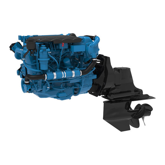
Page 40: Engine Views Z4.205 - Z4.230 - Z4.270
COMPONENTS ENGINE VIEWS Z4.205 - Z4.230 - Z4.270... -
Page 41: S07 Starting & Running
STARTING & RUNNING SUMMARY TABLE DES MATIÈRES STARTING & RUNNING SUMMARY BEFORE STARTING ENGINE INSTALLATION FUEL SYSTEM RAW WATER SYSTEM ELECTRICAL SYSTEM CHECK BEFORE STARTING STARTING THE ENGINE COLD WEATHER OPERATION ENGINE START ENGINE STARTED STARTING WITH BOOSTER BATTERIES ENGINE RELUCTANT TO START IDLING ENGINE NORMAL ENGINE OPERATION BREAK IN... -
Page 42: Before Starting
STARTING & RUNNING BEFORE STARTING RAW WATER SYSTEM The raw water system allows to cool the engine coolant and the exhaust gas. ENGINE INSTALLATION Raw water is drawn into the heat exchanger by the engine raw water pump. The raw water is drained via the See Installation manual exhaust elbow, where it is mixed with exhaust gases. -
Page 43: Check Before Starting
Turn on the engine coolant heater for a minimum of 2 required. hours before starting the engine. Additional information on cold weather operation is available from your Nanni 9. Check there are no fuel, oil, coolant or water leaks. engine distributor or authorized servicing dealer. -
Page 44: Engine Start
STARTING & RUNNING ENGINE START 4. Press the Start button halfway (position 1/2) to start preheating. Hold the button for 10 to 20 seconds, depending on ambient temperature to preheat the With key Type 4 : engine. POSITION 2 1. Move the control lever to the neutral position. POSITION 1/2 : preheating POSITION 1 NEUTRAL... - Page 45 STARTING & RUNNING Electronic type 5: Turn the ignition key to the ON position. On Eco 4, only the oil pressure and battery charge lamp light on. It is not required to start the engine for system initializa- tion. The tachometer will start an autimatic self-test at every powering up.
-
Page 46: Engine Started
STARTING & RUNNING ENGINE STARTED ENGINE RELUCTANT TO START To insure adequate lubrication, operate engine at or If a water lift (water lock) muffler is installed on the below 1200 rpm with no load for 1-2 minutes. Extend exhaust line, excessive cranking could cause seawater this period to 2–4 minutes at freezing or sub-zero to enter the cylinders and damage the engine. -
Page 47: Normal Engine Operation
Any mechanical power taken from the engine from a PTO reduces the power delivered to the propeller. The use of a PTO should always be studied and approved by the R&D department of Nanni Industries S.A.S France. Contact your Nanni dealer for more informations. -
Page 48: Remote Control
Check the instruments and warning lamps after starting, neutral position. and regularly when cruising. Consult the boat builder or your Nanni dealer if you are not sure about the operation of the remote control. -
Page 49: Cruising Speed
STARTING & RUNNING CRUISING SPEED MANOEUVRING A recommended engine speed is given in the TECHNICAL DATA section to help you to set your cruising speed. WARNING ! NOTE ! Shifting at high speed can damage both the engine and the transmission and be dangerous for passengers. Always consider sailing conditions and load of the boat to set the cruising speed. -
Page 50: Engine And Sailing
STARTING & RUNNING ENGINE AND SAILING CAUTION ! When under sail, it is possible to limit the resistance produced by the propeller of the engine. Sailing with the engine stopped and with the lever in neutral must not exceed 6 hours in a row. The propeller can drive the rotation of the shaft and damage the transmission. -
Page 51: After Running
STARTING & RUNNING AFTER RUNNING AFTER STOPPING THE ENGINE STOPPING THE ENGINE CAUTION ! Even after the engine has stopped, some components CAUTION ! and fluids will remain hot and under pressure for several minutes. As far as possible, limit works on the engine Never stop the engine by using the main switch. -
Page 52: Anchoring
STARTING & RUNNING ANCHORING If the boat is not going to be used for some time but is being left in the water, the engine must be run to operating temperature at least once every 2 weeks. This prevents corrosion in the engine. When the boat is at anchor or in port for an extended period of time, vegetation may develop on the hull, the keel, the drive, the rudder, the propeller, etc. -
Page 53: S08 Maintenance
MAINTENANCE SUMMARY Table des matières MAINTENANCE SUMMARY ABOUT MAINTENANCE INTERVALS GENERALITIES CONTROL CABLES TURBOCHARGER AIR INTAKE CHECK THE AIR FILTER CLEANING THE AIR FILTER FUEL SYSTEM DRAIN WATER IN FUEL PREFILTER REPLACING THE FUEL FILTER AIR BLEEDING LUBRICATION SYSTEM OIL LEVEL - ADDING ENGINE OIL DRAINING THE ENGINE OIL CHANGING THE OIL FILTER POWER ASSISTED STEERING OIL LEVEL... -
Page 54: About
During the warranty period, it is essential to get any work carried out by a Nanni authorized workshop. Furthermore, any service should be registered in the Nanni after-sale system. -
Page 55: Maintenance Intervals
MAINTENANCE PERIODICITY MAINTENANCE INTERVALS Every Every Every Maintenance Daily 250 hours 500 hours 1000 hours or 4 30 days COMPONENTS or 1 year ( or 2 years ( years ( or 25 hours ( Fuel Circuit Water in fuel - Pre-filter / Filter Draining Fuel filter replacement Fuel injectors - Check Compensation Value with Diagnostic Tool ( Fuel Mechanical Injectors T6 Engines... -
Page 56: Generalities
MAINTENANCE GENERALITIES CONTROL CABLES The engine rpm and the gearbox shift command may be WARNING ! controlled by mechanical control cables connected to the control lever. Perform maintenance operations having the engine Adjust the tightness of the cable as required. If any stopped and cold. -
Page 57: Turbocharger
MAINTENANCE TURBOCHARGER TURBO SERVICE An engine turbocharger is designed to provide long years of trouble free service, which if required, can only be performed by a specialized workshop. In view CAUTION ! to maintain turbocharger performances for as long as possible, some basic rules must be followed. - Page 58 MAINTENANCE EXHAUST SYSTEM An engine’s exhaust system must be able to freely discharge all high temperature exhaust gas after combustion to the outside air. Exhaust resistance must be as low as possible in order to prevent a decrease in power, however exhaust noise must be kept at an acceptable level.
-
Page 59: Air Intake
MAINTENANCE AIR INTAKE CLEANING THE AIR FILTER Special tool For best results, order the NANNI filter cleaning kit: WARNING ! Number Description Illustration 970317077 Kit air filter cleaner EN, ESP, SUOMI Carry out these operations when the engine is stopped CLEANER and cold. -
Page 60: Fuel System
Any work on the fuel injection system must be carried 5. Open the fuel butterfly (control) valve. out by a authorized Nanni technician. 6. Bleed the fuel system (see in the following Check regularly the condition of the components of the paragraphs). -
Page 61: Replacing The Fuel Filter
MAINTENANCE REPLACING THE FUEL FILTER AIR BLEEDING Bleeding the air in the fuel system might be required : NOTE ! • After a maintenance operation on the fuel system. • If the fuel tank has been emptied. To ease up the air bleeding during fuel filter replacement, •... - Page 62 MAINTENANCE TO BLEED THE FUEL SYSTEM FITTED WITH AN ADDITIONAL ELECTRIC FUEL FEED PUMP: 1. Fill completely the fuel tank. Open the fuel valve. 2. Loose the venting screw . Dispose floorcloths around the venting screw. 3. Start the engine for 5 to 10 seconds to let the electric fuel feed pump bring fuel up to the injection pump.
-
Page 63: Lubrication System
MAINTENANCE LUBRICATION SYSTEM OIL LEVEL - ADDING ENGINE OIL Check the engine and transmission oil level before starting the engine. The oil level should be within the CAUTION ! range indicated on the dipstick, between the Mini and Maxi level. Never over-fill the engine oil crankcase. -
Page 64: Draining The Engine Oil
MAINTENANCE DRAINING THE ENGINE OIL CHANGING THE OIL FILTER PRINCIPLE OF OPERATION : Replace the oil filter every time the engine oil is drained. 1. Start the engine and let it warm a few minutes to render oil more fluid to ease suction. 2. -
Page 65: Power Assisted Steering Oil Level
NANNI workshop. it may indicate a water leak in the Stern drive unit. Check the gear lube with the engine cold, before starting. -
Page 66: Cooling System
Engines designed with an heat exchanger are not sui- The cooling system cools the engine in order to maintain table for a Keel Cooling System (case of T and Z Nanni a proper operating temperature and to prevent overheat- engines series). -
Page 67: Coolant Level
2. Unscrew the filler cap (A) on the exchanger tank on picture below. A specific boiler kit is available from Nanni Industries. Please contact your nearest Nanni representative 3. You may top-up with clean water only, if amount to for more information. -
Page 68: Coolant - Filling
MAINTENANCE DRAINING THE COOLANT CIRCUIT TO FILL THE COOLANT SYSTEM: 1. Stop the engine and remove the key from the panel. 2. Put a container under the drain plug (B) to collect coolant. Unscrew the plug and remove the filler cap on top. -
Page 69: Raw Water System
MAINTENANCE RAW WATER SYSTEM SIPHON BREAKER DANGER ! DANGER ! Close the sea cock before any operation on the siphon When the boat is on the water, water can flow into the breaker. boat via components located below the waterline. Close the raw water cock (if fitted) or prevent water discharge before working on the raw water system. -
Page 70: Extract The Raw Water Pump Impeller
MAINTENANCE EXTRACT THE RAW WATER PUMP IMPELLER TO EXTRACT THE IMPELLER: 1. Stop the engine, remove the key from the panel and close the sea cock. 2. Remove the top cover flange of the raw water pump CAUTION ! (6 screws). 3. -
Page 71: Cleaning The Raw Water Filter
MAINTENANCE CLEANING THE RAW WATER FILTER RAW WATER SYSTEM - DRAINING The model of prefilter can vary according the boat as the raw water filter is an optional extra not in the scope of WARNING ! supply of the engine. These instructions are given as an example only. -
Page 72: Raw Water System - Cleaning
7. At this stage, the raw circuit is alleged to be cleaned up. If deposits and salt crystals are still present, consult your Nanni representative. Do not add up cleaners additives of your own taste, as metal parts are prone to fast corrosion if harshly cleaned. -
Page 73: Electrical System
To charge two independent batteries the alternator and the battery when the engine is running. with a single alternator, an isolator is available as an option on most engines. Contact an authorized Nanni representative. WIRES AND CONNECTORS KEEP CLEAN THE BATTERY Check that electrical wires and connectors are dry and in the Battery(ies) should be kept clean and dry. -
Page 74: Connect The Cables
MAINTENANCE CONNECT THE CABLES ELECTROLYTE LEVEL CHECK 1. Always connect first the positive lead (+) to the Electrolyte level must always be above the top of the positive terminal (+) of the battery lead plates (+/-1 cm - slighlty less than half of an inch). Electrolyte is a mix of sulfuric acid and water. -
Page 75: Alternator Belt
MAINTENANCE ALTERNATOR BELT The engine alternator is driven by a belt through pulleys. These components must be in good order at all times in view for the alternator to provide electricity, among others, to the engine, to the battery, to the engine control panel. -
Page 76: Fuses
If the fault is not resolved quickly, contact your nearest Nanni representative for repair. If you are at open sea, try to locate the fault and to repair The top cover must be removed for full access to the lids by yourself. -
Page 77: Micellaneous
START : Starter motor defect, and must be performed by an authorized Nanni representative. Never let any oil to drop onto the timing belt. Should this happen, have the belt replaced immediately. Do not run the engine without the cover fitted and secured in place. - Page 78 STORAGE SUMMARY Table des matières STORAGE 78 SUMMARY LONG TERM STORAGE LONG TERM STORAGE PROCEDURE RESTARTING THE ENGINE BATTERY...
- Page 79 All these operations 9. Drain any water and contaminants from the fuel tank. should be carried out by a Nanni authorized workshop. 10. Fill totally the fuel tank. 11. Remove the air filter. Secure all air intake with clean clothes.
- Page 80 STORAGE RESTARTING THE ENGINE BATTERY When storing the engine, adjust the battery electrolyte 1. Perform external cleaning of the engine and control level and store it in a dry place at room temperature. its condition. Recharge the battery as often as possible to extend its 2.
- Page 81 CAUTION ! If the engine does not function properly, use the following chart to identify the cause. If the cause of trouble can not be found, contact to Nanni authorized workshop. NOTE ! Some components may not be part of the engine orderes. This list is not exhaustive and is only ab assistance in case of emergencies.
- Page 82 TROUBLESHOOTING Lack of fuel Air in fuel system Fuel filter fouled or clogged Fuel do not meet specified standard Water/contaminants in fuel Valve clearance is wrong * Low compression * Insufficient battery charge / Defective battery Faulty electrical cables contact Faulty starter or starter switch * Tripped fuse / Main switch is open Transmission is damaged*...
- Page 83 Moteur de propulsion PROPULSION ENGINE T4.205-Z4.205 FiCHe teCHniQue DATA SHEET CARACTERISTIQUES GENERALES GENERAL DATA Base moteur Toyota Engine Base Configuration 4 cylindres en ligne Configuration 4 cylinders in line Type 4 temps Diesel Type 4 strokes Diesel Nombre de soupapes par cylindre N°...
- Page 84 T4.205-Z4.205 147.2 kW [200 cv] SYSTEME DE LUBRIFICATION (suite) LUBRIFICATION SYSTEM (continued) litres Capacité d'huile sans filtre, angle 0° Oil quantity excluding filter @ 0° angle gal US 1.95 volant vers le bas Angle d'installation ° front down maxi admissible...
- Page 85 T4.205-Z4.205 147.2 kW [200 cv] SYSTEME DE REFROIDISSEMENT COOLING SYSTEM l/min Débit - liquide de refroidissement Coolant circulation pump flow gal US/min 47.5 l/min Débit - eau brute Raw water pump flow gal US/min 35.1 Chaleur total dégagée à puissance nominale...
- Page 86 The remaining operation time must be at or below cruising speed. NaNNi iNdustries s.a.s. Spécifications selon ISO 3046. Document non contractuel. Soucieuse d’améliorer la qualité de ses produits, Nanni se 11, Avenue Mariotte - Zone Industrielle réserve le droit de modifier, sans préavis, toutes caractéris- tiques énoncées dans ce document.
- Page 87 Moteur de propulsion PROPULSION ENGINE T4.230-Z4.230 FiCHe teCHniQue DATA SHEET CARACTERISTIQUES GENERALES GENERAL DATA Base moteur Toyota Engine Base Configuration 4 cylindres en ligne Configuration 4 cylinders in line Type 4 temps Diesel Type 4 strokes Diesel Nombre de soupapes par cylindre N°...
- Page 88 T4.230-Z4.230 169.1 kW [230 cv] SYSTEME DE LUBRIFICATION (suite) LUBRIFICATION SYSTEM (continued) litres Capacité d'huile sans filtre, angle 0° Oil quantity excluding filter @ 0° angle gal US 1.95 volant vers le bas Angle d'installation ° front down maxi admissible Maximum permitted volant vers le haut °...
- Page 89 T4.230-Z4.230 169.1 kW [230 cv] SYSTEME DE REFROIDISSEMENT COOLING SYSTEM l/min Débit - liquide de refroidissement Coolant circulation pump flow gal US/min 47.5 l/min Débit - eau brute Raw water pump flow gal US/min 35.1 Chaleur total dégagée à puissance nominale Total heat rejection at rated speed BTU/min 15.5...
- Page 90 The remaining operation time must be at or below cruising speed. NaNNi iNdustries s.a.s. Spécifications selon ISO 3046. Document non contractuel. Soucieuse d’améliorer la qualité de ses produits, Nanni se 11, Avenue Mariotte - Zone Industrielle réserve le droit de modifier, sans préavis, toutes caractéris- tiques énoncées dans ce document.
- Page 91 Moteur de propulsion PROPULSION ENGINE T4.270-Z4.270 FiCHe teCHniQue DATA SHEET CARACTERISTIQUES GENERALES GENERAL DATA Base moteur Toyota Engine Base Configuration 4 cylindres en ligne Configuration 4 cylinders in line Type 4 temps Diesel Type 4 strokes Diesel Nombre de soupapes par cylindre N°...
- Page 92 T4.270-Z4.270 194.9 kW [265 cv] SYSTEME DE LUBRIFICATION (suite) LUBRIFICATION SYSTEM (continued) litres Capacité d'huile sans filtre, angle 0° Oil quantity excluding filter @ 0° angle gal US 1.95 volant vers le bas Angle d'installation ° front down maxi admissible Maximum permitted volant vers le haut °...
- Page 93 T4.270-Z4.270 194.9 kW [265 cv] SYSTEME DE REFROIDISSEMENT COOLING SYSTEM l/min Débit - liquide de refroidissement Coolant circulation pump flow gal US/min 47.5 l/min Débit - eau brute Raw water pump flow gal US/min 35.1 Chaleur total dégagée à puissance nominale Total heat rejection at rated speed BTU/min 15.5...
- Page 94 The remaining operation time must be at or below cruising speed. NaNNi iNdustries s.a.s. Spécifications selon ISO 3046. Document non contractuel. Soucieuse d’améliorer la qualité de ses produits, Nanni se 11, Avenue Mariotte - Zone Industrielle réserve le droit de modifier, sans préavis, toutes caractéris- tiques énoncées dans ce document.
- Page 95 This Emission Control System Warranty Statement applies solely to engines certified to United States of America EPA 40 CFR 1042 and sold through Nanni Industries S.A.S - France network (named the "Company") that are instal- led in vessels flagged or registered in the United States of America and associated waters (ie., Pacific & Carribean).
- Page 96 NANNI MARINE DIESEL ENGINES WARRANTY LIMITATIONS ENGINE RESPONSABILITY As far as Nanni Industries S.A.S engines are EPA Nanni engines are assembled and tested in view to certified, it means that the Company guarantees that cause the minimum possible environmental impact.
- Page 98 NaNNi iNdustries s.a.s. 11, Avenue Mariotte 33260 La Teste France Tel: +33 (0)5 56 22 30 60 Fax: +33 (0)5 56 22 30 79 www.nannienergy.com...
Need help?
Do you have a question about the Z4.205 and is the answer not in the manual?
Questions and answers