Table of Contents
Advertisement
Advertisement
Table of Contents

Related Manuals for Nanni N2.10


Summary of Contents for Nanni N2.10
- Page 1 Nanni marine engine Operator’s manual Engines N2.10 N2.14 N3.21...
- Page 2 English You can download a copy of this manual in English on nannidiesel.com. Français Vous pouvez télécharger ce manuel en Français sur notre site Web à l’adresse www.nannidiesel.com. Italiano Scarica una copia del manuale in lingua Italiano sul nannidiesel.com. Deutsch Sie können eine Kopie dieses Handbuchs in Deutsch Sprache auf nanni- diesel.com.
-
Page 3: Table Of Contents
ONTENTS Introduction ......1 Maintenance ......32 About this manual ......2 Service schedule ......33 General inspection ......35 Safety ........3 Fuel system ........37 Emergency kit ......3 Lubrication system .....41 Safety alert symbols .....3 Cooling system ......43 Safety icons ........4 Raw water system ......47 Safety precautions .......5 Electrical system ......51 Overview ........ -
Page 4: Introduction
NTRODUCTION Thank you for choosing a Nanni product! Contact a Nanni authorized dealer for the servicing of your product. A list of dealers can be found on our web site: www.nannidiesel.com Nanni engines are the product of many years of experience in the deve- lopment of marine engines and equipment designed for use in open seas. -
Page 5: About This Manual
About this manual C ontent and updates All the informations and specifica- This Operator’s Manual contains tions in this Manual are based on important information, tips, sugges- the technical data applicable at the tions and warnings. We urge you time of its publication. -
Page 6: Safety
AFETY Safety alert Read this chapter carefully as it concerns your safety. Most acci- symbols dents are caused by failing to follow basic safety rules. Be aware of the General rules of safety precautions possible risks involved in handling to follow are indicated in this Ma- the engine and make sure to take nual. -
Page 7: Safety Icons
Safety icons Indicates where to check the coolant level. Several stickers are fixed directly on the engine. They are intended Indicates where to check the to help you to quickly identify the engine oil level. location of certain components and avoid possible hazards when working on the engine. -
Page 8: Safety Precautions
Safety Burns precautions Never touch the hot parts of the engine! An operational engine gets very hot: the exhaust system, tur- Exhaust gas bocompressor (if equipped), starter, oil sump, oil, coolant in the hoses Exhaust gases contain carbon and pipes are hot and can burn. monoxide. - Page 9 Hazardous Voltage/ Immediately clean up any liquids Electrical Shock spilled and keep the engine com- partment clean and accessible so as to minimise the risk of fire. Be Electrocution is possible whenever careful as fuel can burn. Damaged electricity is present. Hazardous pipes can lead to fire.
-
Page 10: Rotating Parts
Special attention must be brought Ventilate correctly storage batteries on boat with metallic hull, especially compartment. Avoid touching the concerning the protection of the battery terminals with metal tools persons against electrical shock so that no sparks are created which and the protection against galvanic could cause an explosion. - Page 11 Accidental starting tection of the environment. The first protection against water ingress is Accidental starting can cause se- a correct installation of the engine. rious injury and even death! A correct use of the engine is also Disconnect the battery before wor- important to protect the engine king on the engine.
-
Page 12: Overview
VERVIEW About the engine B reak in Operate the engine with care for Engine identification the first 50 hours of operation. Do not race the engine while it is Both the engine and the transmis- cold. Do not operate it at full load sion has an identification plate that except for short periods. - Page 13 Remote Control Power Take Off The remote control is an optional Some engines can be fit with a extra not in the scope of supply Power Take Off system. This sys- of the engine. The remote control tem allows to power accessories installed on the boat can be diffe- like bilge pump, watermaker, etc.
- Page 14 Operation in cold Oil viscosity weather conditions Use seasonal grade viscosity engine oil based on the expected Nanni engines are designed to ope- air temperature range between oil rate effectively in cold weather. changes. However, for effective starting Follow the diagram below to adapt and cold weather operation, extra the oil viscosity: care are necessary.
-
Page 15: Environmental Responsibility
Engine homologation Environmental responsibility The engine type can be exhaust emission certified. It means that Nanni designs its engines to have Nanni guarantees that all engines minimum environmental impact. of the same type that are manufac- This objective, however, can only tured are approved and certified by be achieved with your full coopera- the authorities in accordance with... - Page 16 Warranty Commissioning inspection This manual is supplemented by a Warranty Information Booklet. Commissioning inspection is a We recommend that you read this condition of the validity of the Limi- publication thoroughly. ted Warranty. Moreover, it allows the registration of the product at the Pay special attention to the appli- factory and record important infor- cable duty cycle and to the limita-...
-
Page 17: About The Propeller
A bout the Behaviour of the propeller boat The propeller is a critical compo- If this is your first boat or if you are nent of the propulsion system. It not familiar with the boat, we urge converts the engine power in thrust. you to practice controlling the boat To be efficient, the propeller must at slow speed as a first step. -
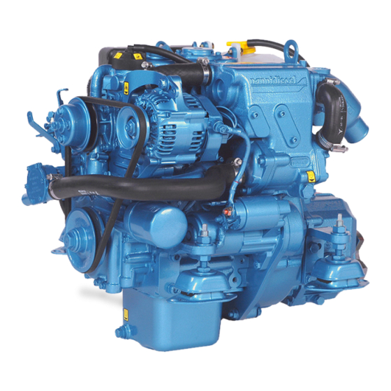
Page 18: Engine Main Components
Engine main components NOTICE: The engine may not be exactly as represented here. Some com- ponents may not be part of the engine ordered. COMPONENTS 1 Alternator 2 Alternator belt 3 Starter 4 Fuses box 5 Air filter 6 Fuel filter 7 Fuel feed pump 8 Fuel injection pump 9 Heat exchanger... - Page 19 N2.10...
- Page 20 N2.14...
- Page 21 N3.21...
-
Page 22: Instruments Panel
NOTICE: The Eco4 panel is only cribes instruments and panels that available with the engine model come standard on Nanni engines. N2.10. Contact your dealer if the boat is fit- ted with instruments not described A4 PANEL in this chapter or if you are not sure about their function. -
Page 23: Instrumentation
The function of the warning lamps is explained in the following pages. NOTICE: As standard, the en- gine model N2.10 is not fit with an electric stop function. A mechanical stop control has to be installed to stop the engine. -
Page 24: Engine Oil Pressure
Engine oil pressure Coolant temperature indicator indicator NOTICE: This indicator does not Indicates the coolant temperature in show the engine oil level. This Celsius and in Fahrenheit degrees. indicator shows the oil pressure in If the coolant temperature is too bar and psi. - Page 25 Warning lamps BATTERY CHARGE COOLANT TEMPERATURE This warning lamp comes on when the system voltage is connected. This warning lamp comes on and If this lamp lights up when the the alarm sounds when the coolant engine is running, it indicates that temperature is too high.
- Page 26 WATER IN FUEL FILTER PREHEATING This lamp lights up and the alarm This lamp comes on when the glow sounds when there is too much plugs (if fitted) are activated. water in the fuel filter of the engine ENGINE OIL PRESSURE (not applicable on some engines).
- Page 27 Note...
-
Page 28: Operation
PERATION Before starting 2. Start the compartment fan (if fitted) for at least five minutes. Otherwise, open the hold. I WARNING 3. Check that there is sufficient Put all the protective covers back fuel. before starting the engine. 4. Move the control lever to the neutral position. -
Page 29: Starting The Engine
Starting the Starting using booster batteries engine I CAUTION I DANGER Make sure to use batteries with The propeller can cause se- the same rated voltage as the rious injury when rotating. Check engine’s system voltage. that nobody is in the water near the propeller before starting. - Page 30 Panel with key Panel without key 1. Move the control lever to the 1. Switch the key of the main pa- neutral position. nel to ignition (if equipped). 2. Push the manual stop control (if 2. Move the control lever to the fitted).
-
Page 31: During Operation
During operation Manoeuvring I WARNING I CAUTION Shifting at high speed can da- Never press the START button mage both the engine and the when the engine is running. transmission and be dangerous for passengers. Check the instruments and warning lamps after starting, and regularly when cruising. - Page 32 Sailing with the engine I CAUTION stopped Sailing with the engine stop- ped and the lever in neutral must not exceed 6 to 7 hours in a row. The propeller can drive the rota- tion of the shaft and damage the transmission.
-
Page 33: Stopping The Engine
Stopping the I CAUTION engine Even after the engine has stopped, some components and I CAUTION fluids remain hot and pressuri- sed for several minutes. As far Never stop the engine by using as possible, limit work on the en- the main switch. - Page 34 Anchoring Storage When the boat is at anchor or in If the boat is being left in the water port for extended period, vegetation while not in use for few weeks, the may develop on the hull, the keel, engine must be controlled and run the drive, the rudder, the propel- few minutes every 10 days.
-
Page 35: Maintenance
AINTENANCE We recommend to have all your I WARNING works checked by a Nanni autho- rized workshop. As far as possible, perform maintenance operations with the Independent repair and adjust- engine stopped, remove the key ment work on the engine beyond a from the panel and turn off the limited scope is forbidden for safety power supply. -
Page 36: Service Schedule
Service schedule NOTICE: An operation requiring service every day requires service after 100 hours or every year, and so on. Some components may not be part of the engine ordered. Operations marked with should be done in a Nanni workshop. * Operations to perform after 20 operating hours or 45 days after commis- sioning. - Page 37 EVERY 200 OPERATING HOURS / AT LEAST EVERY YEAR. Change the engine and transmission oil *. Change the oil filters *. Change the fuel filters *. Check the raw water pump impeller. Change if needed. Check the engine flexible mountings. Adjust as necessary *. ...
-
Page 38: General Inspection
General Stuffing box inspection I DANGER A stuffing box lubricated with I CAUTION raw water taken from the engine Do not let oil, fuel or grease cooling system must never be deposits build up around the installed on a Sail boat or when engine as they may increase the the exhaust elbow is below the risk of fire in the engine compart-... -
Page 39: Exhaust System
Exhaust system The reliability and the performances of the engine depend among other Inspect all exhaust system com- things on the quantity and the tem- ponents (hoses, clamps, mixing perature of the intake air. elbow, manifold, etc.) Check for To check the air filter: cracks, leaks and corrosion. -
Page 40: Fuel System
Fuel system Operation of the fuel system I DANGER The fuel is drawn from the tank by the fuel feed pump and is injected Stop the engine and let it into the combustion chamber by the cool down before refuelling or injection pump. -
Page 41: Fuel Requirements
Fuel requirements Fuel prefilter Only use grade of fuels indicated The fuel prefilter is an optional ex- in the chapter TECHNICAL DATA. tra not in the scope of supply of the Other grades of fuel can increase engine. The model of prefilter can fuel consumption and cause opera- vary according the boat. -
Page 42: Replacing The Fuel Filter
Replacing the fuel filter ENGINE MODEL N2.14 & N3.21 NOTICE: Do not fill the new filter with fuel before assembly. ENGINE MODEL N2.10: N2.14 - N3.21 1. Close the fuel cock. Clean the filter bracket. N2.10 2. Put a plastic bag over the filter 1. - Page 43 Air bleeding To bleed the fuel system IF IT IS FITTED WITH AN ADDITIONAL Bleeding the air in the fuel system ELECTRIC FUEL FEED PUMP : is necessary : 1. Fill totally the fuel tank. Open the fuel cock. • After a maintenance operation on the fuel system.
-
Page 44: Lubrication System
Lubrication The oil level should be within the range indicated on the dipstick, system between the Mini and Max level. To check the oil level: I DANGER 1. Remove and wipe the dipstick. Carry out these operations with 2. Re-insert and remove the the engine stopped and cold. -
Page 45: Draining The Engine Oil
NOTICE: On the engine model N2.10, the oil pump has to be 1. Remove the oil filter with a filter connected to the dipstick port. wrench. Turn the filter counter- clockwise. -
Page 46: Cooling System
Cooling system I CAUTION Engines with heat exchanger Overview are not suitable for a Keel Coo- ling system. The cooling system cools the en- gine in order to maintain a proper Operating the engine without operating temperature and prevent coolant or raw water supply, overheating. - Page 47 Coolant Choose additive that will not have any adverse effects on the mate- rials of the cooling system. Never I CAUTION mix different additive as it may Always use coolant made of cause chemical reactions and the- 50% antifreeze with anticorro- refore malfunctions.
-
Page 48: Coolant Level
Coolant level NOTICE: The Min and Max level indicated on the recovery tank (if fitted) does not indicate the correct I DANGER level of coolant. Never open the coolant filler cap Draining the coolant or any plug of the cooling system when the engine is operating circuit or warm. - Page 49 Coolant - Filling 5. Replace the coolant filler plug and add coolant in the recovery Mix the anti-freeze with water in a tank if necessary. clean container before filling the 6. Start the engine and let it ope- heat exchanger. The coolant must rate few minutes at idle.
-
Page 50: Raw Water System
Raw water system Siphon breaker I DANGER I DANGER Close the sea cock before any When the boat is in the water, operation on the siphon breaker. water can flow into the boat via components located below the waterline. Close the raw water NOTICE: The use of a siphon cock (if fitted) or prevent water breaker is mandatory if the exhaust... - Page 51 Raw water pump impel- 4. Mark the position of the neo- prene impeller inside the pump in order to install it in the correct position in case of reins- I CAUTION tallation. If the engine has been run wi- 5. Carefully remove the impeller thout supply of raw water, check using an extractor.
- Page 52 Cleaning the raw water R aw water system - filter Draining A raw water filter must be fitted I WARNING between the raw water intake and the raw water pump of the engine. It is highly recommended to carry out these operations when The model of prefilter can vary the boat is laid up on land.
- Page 53 Raw water system - 6. Stop the engine. Cleaning and inhibiting 7. Fill the container with engine coolant mix (50% clean water, The raw water system must be 50% anti-freeze). flushed with fresh water to prevent the buildup of deposits and salt 8.
-
Page 54: Electrical System
Electrical system Fuses The engine electrical system is I DANGER protected from electrical overload damage by fuses. Stop the engine and switch off the main switches to break the If the electrical system does not current before working on the work, the engine does not start or electrical system. -
Page 55: Battery
Battery tions for topping up. If the battery electrolyte level is not adjustable (maintenance free battery type), do I DANGER not use or charge the battery if the fluid level stands below the lower Never touch the battery limit level. electrolyte. -
Page 56: Alternator Belt
Alternator belt To adjust the belt tension: I DANGER Stop the engine and remove the key before servicing the alterna- tor belt. Always keep a replacement belt on-board. The alternator belt drives both the coolant pump and the alternator. Additional belt can also be fitted. A loosen or damaged belt can result in overheats or insufficient 1. -
Page 57: Corrosion Protection
Corrosion will wear down in place of other metallic components. protection During the first year of use, check the anodes deterioration every 3 The engine and all metal item in the months. During prolonged moo- boat that are exposed to water or ring near other boats or dock side, damp can be damaged by corro- control the wear and tear of the... - Page 58 Electrolytic corrosion I DANGER Electrolytic corrosion is caused by For engine with a two-pole externally generated DC electrical electrical system, the negative currents that pass through a metal pole of the battery must never item to another in an electrolyte be connected to the common such as raw water.
- Page 59 Engine anode 5. Remove the deposits from the surface of the anode using glass In order to protect the engine and paper before determining the its raw water system from corro- level of erosion. Do not use a soft sion, the engine is fitted with a zinc steel brush as this could leave anode.
-
Page 60: Long Term Storage
Long term Long term storage procedure storage Complete the nearest periodic A set of operations must be per- maintenance inspections and ope- formed to prepare and protect the rations before performing the long engine for a long-term storage. term storage procedure. Refer to the corresponding chapter 1. -
Page 61: Restarting The Engine
6. Remove cloth and tape from I CAUTION openings. Install the air filter. Do not point a high pressure 7. Close/Tighten all plugs and water jet toward seals, hoses, drain cocks. grommets, etc. 8. Check the condition of hoses and clamps. 13. -
Page 62: Troubleshooting
ROUBLESHOOTING If the engine does not function properly, use the following chart to identify the cause. If the cause of trouble can not be found, contact a Nanni autho- rized workshop. NOTICE: Some components may not be part of the engine ordered. This list is not exhaustive and is only an assistance in case of emergencies. - Page 63 1. Lack of fuel 2. Air in fuel system 3. Fuel filter fouled or clogged 4. Fuel do not meet specified standard 5. Water/contaminants in fuel 6. Valve clearance is wrong * 7. Low compression * 8. Insufficient battery charge / Defective battery 9.
-
Page 64: Technical Data
ECHNICAL DATA MODEL N2.10 N2.14 N3.21 ENGINE CHARACTERISTICS Type 4 strokes Diesel Max. power - kW (hp)* 7.36 - 10 10.3 - 14 15.4 - 21 Number of cylinders / Arrangement 2 in line 2 in line 3 in line... - Page 65 MODEL N2.10 N2.14 N3.21 ELECTRICAL SYSTEM Recommended starter battery capa- 35 ~ 50 city (Ah) Starter (kW) Standard Alternator (V-A) 12 - 40 12 - 70 12 - 70 FUEL SYSTEM Injection system Indirect (E-TVCS) Injection timing before TDC (°) Fuel injection pressure (bar) 137.3...
- Page 66 Note...
- Page 68 NANNI INDUSTRIES SAS 11,Avenue Mariotte-Zone Industrielle 33260 La Teste France Tel: + 33 (0)5 56 22 30 60 Fax: +33 (0)5 56 22 30 79 P/N 970316081 Email: contact@nannidiesel.com 082013.IndA www.nannidiesel.com...
Need help?
Do you have a question about the N2.10 and is the answer not in the manual?
Questions and answers
what type no of fuses are used on nanni 10 hp and where are they located