
Subscribe to Our Youtube Channel
Related Manuals for Pfeiffer Vacuum CCR 361


Summary of Contents for Pfeiffer Vacuum CCR 361
- Page 1 OPERATING INSTRUCTIONS Translation of the original instructions CCR 361 … CCR 365 Ceramic Capacitance Gauge...
-
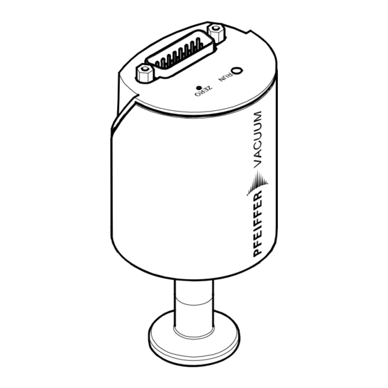
Page 2: Product Identification
Product Identification In all communications with Pfeiffer Vacuum, please specify the information given on the product nameplate. For convenient re- ference copy that information into the space provided below. BG 5135 BEN / D (2019-05) -
Page 3: Validity
The part number (No) can be taken from the product nameplate. If not indicated otherwise in the legends, the illustrations in this document correspond to CCR 361 gauges with the DN 16 ISO-KF vacuum connection. They apply to other vacuum connections by analogy. -
Page 4: Intended Use
We reserve the right to make technical changes without prior notice. All dimensions in mm. Intended Use The Ceramic Capacitance Gauges of the CCR 36X series are intended for absolute pressure measurement of gases in their respective pressure ranges (→ 3). Function The Ceramic Capacitance Gauge consists of a capacitive sensor element made of aluminum oxide ceramics and electronics... -
Page 5: Table Of Contents
Contents Product Identification Validity Intended Use Function Trademark Patents Scope of Delivery Safety 1.1 Symbols Used 1.2 Personnel Qualifications 1.3 General Safety Instructions 1.4 Liability and Warranty Technical Data Installation 3.1 Vacuum Connection 3.2 Power Connection Operation 4.1 Displays 4.2 Zeroing the Gauge 4.3 Activating the Factory Setting (Factory Reset) Deinstallation Maintenance, Repair... -
Page 6: Symbols Used
Safety Symbols Used DANGER Information on preventing any kind of physical injury. WARNING Information on preventing extensive equipment and environ- mental damage. Caution Information on correct handling or use. Disregard can lead to malfunctions or minor equipment damage. Notice Personnel Qualifications Skilled personnel All work described in this document may only be carried out by persons who have suitable technical training and the neces-... -
Page 7: General Safety Instructions
Communicate the safety instructions to all other users. Liability and Warranty Pfeiffer Vacuum assumes no liability and the warranty becomes null and void if the end-user or third parties • disregard the information in this document • use the product in a non-conforming manner •... -
Page 8: Technical Data
Technical Data Measurement range → "Validity" Accuracy PT R27 600 … PT R27 636 0.20% of reading PT R27 646 0.25% of reading PT R27 640 … PT R27 643 0.50% of reading Temperature effect on zero 0.0050% F.S./ °C PT R27 600 …... - Page 9 Supply DANGER The gauge may only be connected to power sup- plies, instruments or control devices that conform to the requirements of a grounded protective extra- low voltage (PELV). The connection to the gauge has to be fused. Supply voltage at the gauge +14 …...
- Page 10 Materials exposed to vacuum Flange, tube stainless steel AISI 316L Sensor and diaphragm ceramics (Al ≥99.5%) Sensor–diaphragm connection glass ceramics solder Ceramics–metal connection AgTiCu hard solder, Vacon 70 (28% Ni, 23% Co, 49% Fe) Internal volume ≤3.6 cm Admissible pressure (absolute) PT R27 600 …...
- Page 11 Dimensions [mm] DN 16 ISO-KF DN 16 CF-R OD½" 8 VCR female Weight ≤370 g BG 5135 BEN / D (2019-05)
- Page 12 Analog Measuring Signal vs. Pressure Pressure p 1.1×F.S. 1.0×F.S. 0.9×F.S. 0.8×F.S. 0.7×F.S. 0.6×F.S. 0.5×F.S. 0.4×F.S. 0.3×F.S. 0.2×F.S. 0.1×F.S. 0.0×F.S. Measuring signal U p = (U / 10 V) × c (F.S.) Conversion Torr ↔ Pascal Torr 1013.25 / 760 = 101325 / 760 = 1.00 1.3332…...
-
Page 13: Vacuum Connection
Installation WARNING WARNING: fragile components The ceramic sensor may be damaged by impacts. Do not drop the product and prevent shocks and impacts. Vacuum Connection DANGER DANGER: overpressure in the vacuum system >100 kPa Injury caused by released parts and harm caused by escaping process gases can result if clamps are opened while the vacuum system is pressurized. - Page 14 DANGER DANGER: protective ground Products that are not correctly connected to ground can be extremely hazardous in the event of a fault. Electrically connect the gauge to the grounded vacuum chamber. This connection must conform to the requirements of a protective connection ac- cording to EN 61010: •...
- Page 15 Mount the gauge so that no vibrations occur. The gauge may be mounted in any orientation. To keep conden- sates and particles from getting into the measuring chamber preferably choose a horizontal to upright posi- tion and possibly use a seal with a centering ring and filter.
-
Page 16: Power Connection
Power Connection Make sure the vacuum connection is properly made (→ 13). DANGER The gauge may only be connected to power sup- plies, instruments or control devices that conform to the requirements of a grounded protective extra- low voltage (PELV). The connection to the gauge has to be fused. - Page 17 If no sensor cable is available, make one according to the following diagram. Ident 10Ω case Electrical connection Pin 2 Signal Output Pin 5 Supply common, GND Pin 7, 11 Supply Pin 10 Gauge identification Pin 12 Signal common Pin 15 Housing (Chassis Ground) case...
-
Page 18: Displays
Operation Put the gauge into operation. Warm-up time >¼ hour • for general purpose reading (within specifications) >2 hours • for zero adjustment and precision measurement Displays ZERO State Meaning Measurement mode <RUN> flashing Other mode, error, under/overrange Zeroing the Gauge The gauge is factory calibrated while "standing upright"... - Page 19 <ZERO> Adjustment 4.2.1 Evacuate the gauge to a pressure according to the table below: Recommended final pressure for zero adjustment CCR 361 <5 Torr <7 <7 mbar × × ×...
- Page 20 Briefly press the <ZERO> button with a pin (max. ø1.1 mm). The zero adjustment runs automatically. The <RUN> LED flashes until the adjustment (duration ≤8 s) is completed. Press the button briefly max. ø1.1 mm After zero adjustment the gauge automatically returns to measurement mode.
- Page 21 It also permits to adjust an offset of the characteristic curve in order to • compensate for the offset of the measuring system or • obtain a slightly positive zero for a 0 … 10 V AD-converter. The offset should not exceed 2% of the F.S. (+200 mV). At a higher positive offset, the upper limit of the measuring range is exceeded.
-
Page 22: Activating The Factory Setting (Factory Reset)
Push the <ZERO> button again: Fine adjustment the zero adjustment value changes within 0...3 s: by one unit (push <ZERO> button in intervals of 1 s) Change of direction the zero adjustment changes its within 3...5 s: direction (the flashing frequency of the <RUN>... -
Page 23: Deinstallation
Deinstallation WARNING WARNING: fragile components The ceramic sensor may be damaged by impacts. Do not drop the product and prevent shocks and impacts. DANGER DANGER: contaminated parts Contaminated parts can be detrimental to health and environment. Before beginning to work, find out whether any parts are contaminated. -
Page 24: Maintenance, Repair
We recommend checking the zero at regular intervals (→ 19). Pfeiffer Vacuum assumes no liability and the warranty becomes null and void if any repair work is carried out by the end-user or third parties. BG 5135 BEN / D... -
Page 25: Returning The Product
Contaminated products (e.g. radioactive, toxic, caustic or microbiological hazard) can be detrimen- tal to health and environment. Products returned to Pfeiffer Vacuum should pre- ferably be free of harmful substances. Adhere to the forwarding regulations of all involved countries and forwarding companies and enclose a duly completed declaration of contamination * Form under www.pfeiffer-vacuum.com... -
Page 26: Conversion Table
WARNING WARNING: substances detrimental to the environ- ment Products or parts thereof (mechanical and electric components, operating fluids etc.) can be detrimen- tal to the environment. Dispose of such substances in accordance with the relevant local regulations. Separating the components After disassembling the product, separate its components ac- cording to the following criteria: •... -
Page 27: Etl Listed
ETL Listed ETL LISTED The products CCR 361 … CCR 365 • conform to the UL Standard UL 61010-1 • are certified to the CSA Standard CSA C22.2 # 61010-1 BG 5135 BEN / D (2019-05) -
Page 28: Eu Declaration Of Conformity
EU Declaration of Conformity We, Pfeiffer Vacuum, hereby declare that the equipment men- tioned below comply with the following directives: • 2014/30/EU, OJ L 96/79, 29.3.2014 (EMC directive; Directive relating to electromagnetic compatibility) • 2011/65/EU, OJ L 174/88, 1.7.2011 (RoHS directive; Directive on the restriction of the use of certain hazard-... - Page 29 VACUUM SOLUTIONS FROM A SINGLE SOURCE Pfeiffer Vacuum stands for innovative and custom vacuum solutions worldwide, technological perfection, competent advice and reliable service. COMPLETE RANGE OF PRODUCTS From a single component to complex systems: We are the only supplier of vacuum technology that provides a complete product portfolio.
Need help?
Do you have a question about the CCR 361 and is the answer not in the manual?
Questions and answers