
Related Manuals for Dell Inspiron 13-5368


Summary of Contents for Dell Inspiron 13-5368
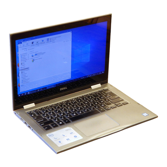
- Page 1 Inspiron 13 5000 Series 2-in-1 Service Manual Computer Model: Inspiron 13-5368 Regulatory Model: P69G Regulatory Type: P69G001...
- Page 2 © 2016 Dell Inc. All rights reserved. This product is protected by U.S. and international copyright and intellectual property laws. Dell and the Dell logo are trademarks of Dell Inc. in the United States and/or other jurisdictions. All other marks and names mentioned herein may be trademarks of their respective companies.
-
Page 3: Table Of Contents
Contents Before working inside your computer........12 .....................12 Before you begin ....................12 Safety instructions ..................13 Recommended tools After working inside your computer........15 Removing the base cover............16 ......................16 Procedure Replacing the base cover............19 ......................19 Procedure Removing the battery...............20 ....................20 Prerequisites ...................... - Page 4 Removing the hard drive............29 .....................29 Prerequisites ......................29 Procedure Replacing the hard drive............32 ......................32 Procedure ....................32 Post-requisites Removing the coin-cell battery..........33 .....................33 Prerequisites ......................33 Procedure Replacing the coin-cell battery..........35 ......................35 Procedure ....................35 Post-requisites Removing the wireless card............ 36 .....................36 Prerequisites ......................
- Page 5 Removing the speakers............43 .....................43 Prerequisites ......................43 Procedure Replacing the speakers............45 ......................45 Procedure ....................45 Post-requisites Removing the fan..............46 ....................46 Prerequisites ......................46 Procedure Replacing the fan..............48 ......................48 Procedure ....................48 Post-requisites Removing the heat sink............49 ....................
- Page 6 Removing the status-light board........... 55 .....................55 Prerequisites ......................55 Procedure Replacing the status-light board..........58 ......................58 Procedure ....................58 Post-requisites Removing the touch pad............59 .....................59 Prerequisites ......................59 Procedure Replacing the touch pad............63 ......................63 Procedure ....................63 Post-requisites Removing the I/O board............64 ....................
- Page 7 Removing the power-adapter port........72 .....................72 Prerequisites ......................72 Procedure Replacing the power-adapter port........74 ......................74 Procedure ....................74 Post-requisites Removing the system board............75 .....................75 Prerequisites ......................75 Procedure Replacing the system board............ 79 ......................79 Procedure ....................79 Post-requisites ........80 Entering the Service Tag in the BIOS setup program Removing the palm rest and keyboard assembly....81 .....................81 Prerequisites...
- Page 8 Removing the display back-cover and antenna assembly..................88 ....................88 Prerequisites ......................88 Procedure Replacing the display back-cover and antenna assembly..................90 ......................90 Procedure ....................90 Post-requisites Removing the camera...............91 ..................... 91 Prerequisites ......................91 Procedure Replacing the camera...............93 ......................93 Procedure ....................
- Page 9 Changing the audio settings ......................102 Camera ........... 102 Identifying the webcam in device manager .............. 102 Starting the camera application ............103 Getting the Dell Webcam Central ......................104 Display ................104 Adjusting the brightness ..............104 Changing the screen resolution ................. 105 Rotating the display ................
- Page 10 ..................113 Configuring Wi-Fi ......................113 Bluetooth ..............114 Turning on or off Bluetooth ...........114 Pairing the Bluetooth-enabled devices .............. 115 Removing the Bluetooth device .......115 Transferring files between devices using Bluetooth .......................116 Hard Drive ................. 116 Identifying the hard drive ........117 Identifying the hard drive in BIOS setup program ..................117...
- Page 11 Intel Wireless 3165 WiFi and Bluetooth drivers ....................131 BIOS overview ............131 Entering the BIOS setup program ....................131 Boot menu ..............131 Boot menu enhancements ................131 Timing key sequences System diagnostic lights............132 Getting help and contacting Dell.........134 ..................134 Self-help resources ....................135 Contacting Dell...
-
Page 12: Before Working Inside Your Computer
Before working inside your computer NOTE: The images in this document may differ from your computer depending on the configuration you ordered. Before you begin Save and close all open files and exit all open applications. Shut down your computer. The shut-down instruction varies depending on the operating system installed on your computer. -
Page 13: Recommended Tools
CAUTION: You should only perform troubleshooting and repairs as authorized or directed by the Dell technical assistance team. Damage due to servicing that is not authorized by Dell is not covered by your warranty. See the safety instructions that shipped with the product or at www.dell.com/regulatory_compliance. - Page 14 • Plastic scribe...
-
Page 15: After Working Inside Your Computer
After working inside your computer CAUTION: Leaving stray or loose screws inside your computer may severely damage your computer. Replace all screws and ensure that no stray screws remain inside your computer. Connect any external devices, peripherals, or cables you removed before working on your computer. -
Page 16: Removing The Base Cover
Before working inside your computer. After working inside your computer, follow the instructions in After working inside your computer. For more safety best practices, see the Regulatory Compliance home page at www.dell.com/regulatory_compliance. Procedure Close the display and turn the computer over. - Page 17 Remove the screws that secure the base cover to the palm-rest assembly. screws (9) base cover palm-rest assembly...
- Page 18 Using a plastic scribe, release the tabs that secure the base cover to the palm-rest assembly and remove the base cover off the palm-rest assembly. plastic scribe palm-rest assembly base cover...
-
Page 19: Replacing The Base Cover
After working inside your computer. For more safety best practices, see the Regulatory Compliance home page at www.dell.com/regulatory_compliance. Procedure Align the base cover with the palm-rest assembly and snap it into place. Replace the screws that secure the base cover to the palm-rest assembly. -
Page 20: Removing The Battery
Before working inside your computer. After working inside your computer, follow the instructions in After working inside your computer. For more safety best practices, see the Regulatory Compliance home page at www.dell.com/regulatory_compliance. Prerequisites Remove the base cover. Procedure Disconnect the battery cable from the system board. - Page 21 Lift the battery off the palm-rest assembly. system board battery cable screws (4) palm-rest assembly battery Press and hold the power button for five seconds to ground the system board.
-
Page 22: Replacing The Battery
After working inside your computer. For more safety best practices, see the Regulatory Compliance home page at www.dell.com/regulatory_compliance. Procedure Align the screw holes on the battery with the screw holes on the palm- rest assembly. -
Page 23: Removing The Memory Modules
Before working inside your computer. After working inside your computer, follow the instructions in After working inside your computer. For more safety best practices, see the Regulatory Compliance home page at www.dell.com/regulatory_compliance. Prerequisites Remove the base cover. Remove the battery. -
Page 24: Procedure
Procedure Lift the Mylar to access the memory module. memory module Mylar Use your fingertips to carefully spread apart the securing-clips on each end of the memory-module slot until the memory module pops up. - Page 25 Remove the memory module from the memory-module slot. securing clips (2) memory module memory-module slot...
-
Page 26: Replacing The Memory Modules
After working inside your computer. For more safety best practices, see the Regulatory Compliance home page at www.dell.com/regulatory_compliance. Procedure Lift the Mylar to access the memory-module slot. Align the notch on the memory module with the tab on the memory-... -
Page 27: Post-Requisites
Slide the memory module firmly into the slot at an angle and press the memory module down until it clicks into place. NOTE: If you do not hear the click, remove the memory module and reinstall it. memory module memory-module slot notch Mylar Post-requisites... - Page 28 Replace the base cover.
-
Page 29: Removing The Hard Drive
After working inside your computer. For more safety best practices, see the Regulatory Compliance home page at www.dell.com/regulatory_compliance. CAUTION: Hard drives are fragile. Exercise care when handling the hard drive. CAUTION: To avoid data loss, do not remove the hard drive while the computer is in sleep or on state. - Page 30 Lift the hard-drive assembly, along with its cable, off the palm-rest assembly. tape hard-drive assembly palm-rest assembly screws (2) system board hard-drive cable pull tab...
- Page 31 Disconnect the interposer from the hard-drive assembly. interposer hard-drive assembly Remove the screws that secure the hard-drive bracket to the hard drive. Lift the hard-drive bracket off the hard drive. screws (4) hard-drive bracket hard drive...
-
Page 32: Replacing The Hard Drive
After working inside your computer, follow the instructions in After working inside your computer. For more safety best practices, see the Regulatory Compliance home page at www.dell.com/regulatory_compliance. CAUTION: Hard drives are fragile. Exercise care when handling the hard drive. Procedure Align the screw holes on the hard-drive bracket with the screw holes on the hard drive. -
Page 33: Removing The Coin-Cell Battery
After working inside your computer. For more safety best practices, see the Regulatory Compliance home page at www.dell.com/regulatory_compliance. CAUTION: Removing the coin-cell battery resets the BIOS setup program’s settings to default. It is recommended that you note the BIOS setup program’s settings before removing the coin-cell battery. - Page 34 Peel the coin-cell battery off the palm-rest assembly. I/O board coin-cell battery cable coin-cell battery palm-rest assembly...
-
Page 35: Replacing The Coin-Cell Battery
After working inside your computer. For more safety best practices, see the Regulatory Compliance home page at www.dell.com/regulatory_compliance. Procedure Adhere the coin-cell battery to the palm-rest assembly. Connect the coin-cell battery cable to the I/O board. -
Page 36: Removing The Wireless Card
Before working inside your computer. After working inside your computer, follow the instructions in After working inside your computer. For more safety best practices, see the Regulatory Compliance home page at www.dell.com/regulatory_compliance. Prerequisites Remove the base cover. Remove the battery. - Page 37 Slide and remove the wireless card from the wireless-card slot. screw wireless-card bracket wireless-card slot wireless card antenna cables (2)
-
Page 38: Replacing The Wireless Card
After working inside your computer, follow the instructions in After working inside your computer. For more safety best practices, see the Regulatory Compliance home page at www.dell.com/regulatory_compliance. Procedure CAUTION: To avoid damage to the wireless card, do not place any cables under it. -
Page 39: Post-Requisites
Replace the screw that secures the wireless card bracket to the wireless card. notch wireless-card slot wireless card antenna cables (2) wireless card bracket screw Post-requisites Replace the battery. Replace the base cover. -
Page 40: Removing The Keyboard Daughter-Board
Before working inside your computer. After working inside your computer, follow the instructions in After working inside your computer. For more safety best practices, see the Regulatory Compliance home page at www.dell.com/regulatory_compliance. Prerequisites Remove the base cover. Remove the battery. - Page 41 Using a plastic scribe, pry the keyboard daughter-board off the palm-rest assembly. keyboard cable palm-rest assembly touch-pad cable keyboard daughter-board cable latch status-light board-cable plastic scribe keyboard daughter-board...
-
Page 42: Replacing The Keyboard Daughter-Board
After working inside your computer. For more safety best practices, see the Regulatory Compliance home page at www.dell.com/regulatory_compliance. Procedure Adhere the keyboard daughter board on the palm-rest assembly. Connect the keyboard cable, keyboard daughter-board cable, touch-pad cable, and status-light board-cable and close the latches to secure the cables. -
Page 43: Removing The Speakers
Before working inside your computer. After working inside your computer, follow the instructions in After working inside your computer. For more safety best practices, see the Regulatory Compliance home page at www.dell.com/regulatory_compliance. Prerequisites Remove the base cover. Remove the battery. - Page 44 Remove the speakers from the alignment posts and lift the speakers off the palm-rest assembly. system board speaker cable palm-rest assembly routing guides tape (3) alignment posts speakers (2) rubber grommets (5)
-
Page 45: Replacing The Speakers
After working inside your computer. For more safety best practices, see the Regulatory Compliance home page at www.dell.com/regulatory_compliance. Procedure NOTE: The rubber grommets may get pushed out while replacing the speaker. Ensure that the rubber grommets are in their position after placing the speaker on the palm-rest assembly. -
Page 46: Removing The Fan
Before working inside your computer. After working inside your computer, follow the instructions in After working inside your computer. For more safety best practices, see the Regulatory Compliance home page at www.dell.com/regulatory_compliance. Prerequisites Remove the base cover. Remove the battery. - Page 47 Lift the fan off the palm-rest assembly. palm-rest assembly screws (2) fan cable system board...
-
Page 48: Replacing The Fan
After working inside your computer, follow the instructions in After working inside your computer. For more safety best practices, see the Regulatory Compliance home page at www.dell.com/regulatory_compliance. Procedure Align the screw holes on the fan with the screw holes on the palm-rest assembly. -
Page 49: Removing The Heat Sink
After working inside your computer. For more safety best practices, see the Regulatory Compliance home page at www.dell.com/regulatory_compliance. WARNING: The heat sink may become hot during normal operation. Allow sufficient time for the heat sink to cool before you touch it. - Page 50 Lift the heat sink off the system board. heat sink captive screws (4) system board...
-
Page 51: Replacing The Heat Sink
After working inside your computer. For more safety best practices, see the Regulatory Compliance home page at www.dell.com/regulatory_compliance. CAUTION: Incorrect alignment of the heat sink can damage the system board and processor. NOTE: The original thermal grease can be reused if the original system board and heat sink are reinstalled together. -
Page 52: Removing The Power And Volume-Buttons Board
Before working inside your computer. After working inside your computer, follow the instructions in After working inside your computer. For more safety best practices, see the Regulatory Compliance home page at www.dell.com/regulatory_compliance. Prerequisites Remove the base cover. Remove the battery. - Page 53 Lift the power and volume-buttons board off the palm-rest assembly. tape power and volume- buttons board-cable routing guides (2) power and volume- buttons board screw palm-rest assembly...
-
Page 54: Replacing The Power And Volume-Buttons Board
After working inside your computer. For more safety best practices, see the Regulatory Compliance home page at www.dell.com/regulatory_compliance. Procedure Align the screw hole on the power and volume-buttons board with the screw hole on the palm-rest assembly. -
Page 55: Removing The Status-Light Board
Before working inside your computer. After working inside your computer, follow the instructions in After working inside your computer. For more safety best practices, see the Regulatory Compliance home page at www.dell.com/regulatory_compliance. Prerequisites Remove the base cover. Remove the battery. - Page 56 Lift the speaker cable off the status-light board. tape (2) speaker cable routing guides palm-rest assembly Open the latch and disconnect the status-light board-cable from the keyboard daughter-board.
- Page 57 Lift the status-light board off the palm-rest assembly. latch status-light board-cable keyboard daughter-board status-light board...
-
Page 58: Replacing The Status-Light Board
After working inside your computer, follow the instructions in After working inside your computer. For more safety best practices, see the Regulatory Compliance home page at www.dell.com/regulatory_compliance. Procedure Align and place the status-light board in the slot on the palm-rest assembly. -
Page 59: Removing The Touch Pad
Before working inside your computer. After working inside your computer, follow the instructions in After working inside your computer. For more safety best practices, see the Regulatory Compliance home page at www.dell.com/regulatory_compliance. Prerequisites Remove the base cover. Remove the battery. - Page 60 Open the latches and disconnect the touch-pad cable from the touch pad and the keyboard daughter-board. system board keyboard daughter-board cable latch touch-pad cable keyboard daughter-board palm-rest assembly Peel off the pieces of tape that secure the touch-pad to the palm-rest assembly.
- Page 61 Lift the touch-pad bracket off the palm-rest assembly. screws (4) palm-rest assembly touch-pad bracket tape (2) Remove the screws that secure the touch pad to the palm-rest assembly.
- Page 62 Lift the touch pad off the palm-rest assembly. screws (4) palm-rest assembly touch pad...
-
Page 63: Replacing The Touch Pad
After working inside your computer. For more safety best practices, see the Regulatory Compliance home page at www.dell.com/regulatory_compliance. Procedure Place the touch pad on the palm-rest assembly. Align the screw holes on the touch pad with the screw holes on the palm-rest assembly. -
Page 64: Removing The I/O Board
Before working inside your computer. After working inside your computer, follow the instructions in After working inside your computer. For more safety best practices, see the Regulatory Compliance home page at www.dell.com/regulatory_compliance. Prerequisites Remove the base cover. Remove the battery. - Page 65 Lift the I/O board off the palm-rest assembly. I/O board tape I/O-board cable screws (2) latch palm-rest assembly coin-cell battery-cable tape power and volume-buttons board-cable...
-
Page 66: Replacing The I/O Board
After working inside your computer. For more safety best practices, see the Regulatory Compliance home page at www.dell.com/regulatory_compliance. Procedure Place the I/O board on the palm-rest assembly. Align the screw hole on the I/O board with the screw hole on the palm- rest assembly. -
Page 67: Removing The Display Assembly
Before working inside your computer. After working inside your computer, follow the instructions in After working inside your computer. For more safety best practices, see the Regulatory Compliance home page at www.dell.com/regulatory_compliance. Prerequisites Remove the base cover. Remove the battery. - Page 68 Open the latches to disconnect the display cable and the touch-screen board-cable from the system board. antenna cables (2) display cable touch-screen board-cable latch tape (2) Turn the computer over and open the display as far as possible. CAUTION: Place the computer on a soft and clean surface to avoid scratching the display.
- Page 69 Remove the screws that secure the display assembly to the palm-rest assembly. display assembly screws (4) display hinges (2) palm-rest assembly...
- Page 70 Lift the display assembly off the palm-rest assembly. display assembly...
-
Page 71: Replacing The Display Assembly
After working inside your computer, follow the instructions in After working inside your computer. For more safety best practices, see the Regulatory Compliance home page at www.dell.com/regulatory_compliance. Procedure CAUTION: Place the computer on a soft and clean surface to avoid scratching the display. -
Page 72: Removing The Power-Adapter Port
Before working inside your computer. After working inside your computer, follow the instructions in After working inside your computer. For more safety best practices, see the Regulatory Compliance home page at www.dell.com/regulatory_compliance. Prerequisites Remove the base cover. Remove the battery. - Page 73 Lift the power-adapter port off the palm-rest assembly. power-adapter port-cable screw power adapter port system board palm-rest assembly...
-
Page 74: Replacing The Power-Adapter Port
After working inside your computer. For more safety best practices, see the Regulatory Compliance home page at www.dell.com/regulatory_compliance. Procedure Place the power-adapter port into the slot on the palm-rest assembly. Align the screw hole on the power-adapter port with the screw hole on the palm-rest assembly. -
Page 75: Removing The System Board
After working inside your computer. For more safety best practices, see the Regulatory Compliance home page at www.dell.com/regulatory_compliance. NOTE: Your computer’s Service Tag is stored in the system board. You must enter the Service Tag in the BIOS setup program after you replace the system board. - Page 76 Peel off the tape that secures the I/O-board cable to the system board. I/O-board cable display cable tape (3) touch-screen cable system board Open the latches to disconnect the display cable and the touch-screen board-cable from the system board. Open the latch to disconnect the I/O-board cable from the system board.
- Page 77 Disconnect the hard-drive cable from the system board. display cable touch-screen cable tape power adapter port-cable speaker cable latch keyboard daughter-board hard-drive cable cable I/O-board cable 10 tape Remove the screws that secure the system board to the palm-rest assembly.
- Page 78 Lift the system board off the palm-rest assembly. screw system board palm-rest assembly...
-
Page 79: Replacing The System Board
After working inside your computer. For more safety best practices, see the Regulatory Compliance home page at www.dell.com/regulatory_compliance. NOTE: Your computer’s Service Tag is stored in the system board. You must enter the Service Tag in the BIOS setup program after you replace the system board. -
Page 80: Entering The Service Tag In The Bios Setup Program
Entering the Service Tag in the BIOS setup program Turn on or restart your computer. Press F2 when the Dell logo is displayed to enter the BIOS setup program. Navigate to the Main tab and enter the Service Tag in the Service Tag Input field. -
Page 81: Removing The Palm Rest And Keyboard Assembly
Before working inside your computer. After working inside your computer, follow the instructions in After working inside your computer. For more safety best practices, see the Regulatory Compliance home page at www.dell.com/regulatory_compliance. Prerequisites Remove the base cover. Remove the battery. - Page 82 palm rest...
-
Page 83: Replacing The Palm Rest And Keyboard Assembly
After working inside your computer, follow the instructions in After working inside your computer. For more safety best practices, see the Regulatory Compliance home page at www.dell.com/regulatory_compliance. Procedure Place the palm-rest and keyboard assembly on a flat surface with the keyboard facing down. -
Page 84: Removing The Display Panel
Before working inside your computer. After working inside your computer, follow the instructions in After working inside your computer. For more safety best practices, see the Regulatory Compliance home page at www.dell.com/regulatory_compliance. Prerequisites Remove the base cover. Remove the battery. - Page 85 Using a plastic scribe, pry the display-panel assembly off the display back-cover and antenna assembly. plastic scribe display back-cover routing guides display cable hinge covers display panel Turn over the display-panel assembly. Remove the camera.
- Page 86 Remove the sensor board. After performing the above steps, we are left with the display panel. display panel...
-
Page 87: Replacing The Display Panel
After working inside your computer, follow the instructions in After working inside your computer. For more safety best practices, see the Regulatory Compliance home page at www.dell.com/regulatory_compliance. Procedure Place the display panel on a flat surface. Replace the sensor board. -
Page 88: Removing The Display Back-Cover And Antenna Assembly
Before working inside your computer. After working inside your computer, follow the instructions in After working inside your computer. For more safety best practices, see the Regulatory Compliance home page at www.dell.com/regulatory_compliance. Prerequisites Remove the base cover. Remove the battery. - Page 89 display back-cover and antenna antenna cables assembly...
-
Page 90: Replacing The Display Back-Cover And Antenna Assembly
After working inside your computer, follow the instructions in After working inside your computer. For more safety best practices, see the Regulatory Compliance home page at www.dell.com/regulatory_compliance. Procedure Place the display back-cover and antenna assembly on a flat surface. Post-requisites... -
Page 91: Removing The Camera
Before working inside your computer. After working inside your computer, follow the instructions in After working inside your computer. For more safety best practices, see the Regulatory Compliance home page at www.dell.com/regulatory_compliance. Prerequisites Remove the base cover. Remove the battery. - Page 92 Turn the camera over and peel off the tape to disconnect the camera cable from the camera module. display panel plastic scribe camera module camera cable tape...
-
Page 93: Replacing The Camera
After working inside your computer. For more safety best practices, see the Regulatory Compliance home page at www.dell.com/regulatory_compliance. Procedure Connect the camera cable to the camera module. Adhere the tape that secures the camera cable to the camera module. -
Page 94: Removing The Display Cable
Before working inside your computer. After working inside your computer, follow the instructions in After working inside your computer. For more safety best practices, see the Regulatory Compliance home page at www.dell.com/regulatory_compliance. Prerequisites Remove the base cover. Remove the battery. - Page 95 Lift the display cable off the display panel. tape sensor-board cable tape sensor-board cable display cable latch display panel...
-
Page 96: Replacing The Display Cable
After working inside your computer. For more safety best practices, see the Regulatory Compliance home page at www.dell.com/regulatory_compliance. Procedure Route the display cable through the routing guides on the display panel. Slide the display cable into the connector and press down the latch to secure the cable. -
Page 97: Removing The Sensor Board
Before working inside your computer. After working inside your computer, follow the instructions in After working inside your computer. For more safety best practices, see the Regulatory Compliance home page at www.dell.com/regulatory_compliance. Prerequisites Remove the base cover. Remove the battery. - Page 98 Lift the sensor board off the display panel. sensor board screw tape sensor-board cable latch...
-
Page 99: Replacing The Sensor Board
After working inside your computer. For more safety best practices, see the Regulatory Compliance home page at www.dell.com/regulatory_compliance. Procedure Align the screw hole on the sensor board to the display panel and snap the sensor board in place. -
Page 100: Flashing The Bios
You may need to flash (update) the BIOS when an update is available or when you replace the system board. To flash the BIOS: Turn on your computer. Go to www.dell.com/support. Click or tap Product support, enter the Service Tag of your computer, and then click or tap Submit. -
Page 101: Technology And Components
Downloading the audio driver Turn on your computer. Go to www.dell.com/support. Click or tap Product support, enter the Service Tag of your computer and then click or tap Submit. NOTE: If you do not have the Service Tag, use the auto-detect feature or manually browse for your computer model. -
Page 102: Changing The Audio Settings
Before installation After installation Changing the audio settings On the taskbar, click or tap the search box, and then type Dell Audio. Click or tap Dell Audio and change the audio settings as required. Camera The Inspiron 13-5368 is shipped with an integrated 0.92 megapixel high- speed camera with a maximum of 1280 X 720 HD resolution at 30 FPS. -
Page 103: Getting The Dell Webcam Central
Click or tap Camera. Getting the Dell Webcam Central A CD is shipped along with your computer, which contains the Dell Webcam Central software. If you do not have the software, you can download it by registering through My Account on the Dell website. -
Page 104: Display
Display The Inspiron 13-5368 is shipped with the following display options: • 13.3-inch HD WLED touch with 1366 X 768 resolution • 13.3-inch FHD WLED touch screen with 1920 X 1080 resolution Adjusting the brightness Right-click or touch and hold on your desktop and select Display settings. -
Page 105: Rotating The Display
Click or tap Apply. Rotating the display Right-click or touch and hold on your desktop. Select Graphics Options → Rotation and select from the following options: – Rotate to 0 Degrees – Rotate to 90 Degrees – Rotate to 180 Degrees –... -
Page 106: Cleaning The Display
Let the display dry thoroughly before turning it on. HDMI The Inspiron 13-5368 supports HDMI to connect a TV or another HDMI-in enabled device. It provides video and audio output. The HDMI port is located on the left side of your computer. - Page 107 Select one of the following display modes: – PC screen only – Duplicate – Extend – Second screen only NOTE: For more information, see the document that shipped with your display device.
-
Page 108: Graphics
Graphics The Inspiron 13-5368 is shipped with the following video controllers: • Intel HD Graphics 510 - Intel Celeron and Pentium (Shared system memory) • Intel HD Graphics 520 - Intel Core i3/i5/i7 (Shared system memory) • Intel Iris Graphics 540 - Intel Core i7 (Shared system memory) Downloading the graphics driver Turn on your computer. -
Page 109: Changing The Display Settings In Intel Hd Graphics Control Panel
Changing the display settings in Intel HD Graphics Control Panel Right-click or touch and hold on the desktop and select Graphics Properties to launch the Intel HD Graphics Control Panel. Click or tap Display. Change the display settings as required. Intel WiDi The wireless display feature allows you to share your computer display with a compatible TV without using cables. -
Page 110: Downloading The Widi Application
Downloading the WiDi application Turn on your computer. Go to www.dell.com/support. Click or tap Product Support, enter the Service Tag of your computer and click or tap Submit. NOTE: If you do not have the Service Tag, use the auto-detect feature or manually browse for your computer model. -
Page 111: Usb
Enabling or disabling the USB in BIOS setup program Turn on or restart your computer. Press F2 when the Dell logo is displayed on the screen to enter the BIOS setup program. The BIOS setup program is displayed. -
Page 112: Fixing A No-Boot Issue Caused By Usb Emulation
USB devices. Follow these steps to fix the no-boot issue: Turn on or restart your computer. Press F2 when the Dell logo is displayed on the screen to enter the BIOS setup program. The BIOS setup program is displayed. -
Page 113: Configuring Wi-Fi
Right-click or touch and hold Wi-Fi, and then click or tap Go to settings. A list of available networks is displayed. Select your network and click or tap Connect. NOTE: Type the network security key, if prompted. Bluetooth The Inspiron 13-5368 is shipped with Bluetooth 4.0 and Bluetooth 4.1 (optional). -
Page 114: Turning On Or Off Bluetooth
Turning on or off Bluetooth NOTE: There is no physical switch to enable or disable Bluetooth. It has to be done through the computer settings. Swipe-in from the right edge of the display, or click or tap the Action Center icon on the task bar to access the Action Center. Click or tap Bluetooth to turn Bluetooth on or off. -
Page 115: Removing The Bluetooth Device
Click or tap Yes to confirm the passcodes on both the devices. Removing the Bluetooth device Swipe-in from the right edge of the display, or click or tap the Action Center icon on the task bar to access the Action Center. Right-click or touch and hold Bluetooth, and then click or tap Go to settings. -
Page 116: Hard Drive
Right-click or touch and hold Bluetooth, and then click or tap Go to settings. Select your Bluetooth device. Click or tap Send or receive files via Bluetooth. In the Bluetooth File Transferwindow, click or tap Send files, and then select the file you want to transfer. Hard Drive The following table shows the hard-drive options available in Inspiron 13-5368. -
Page 117: Identifying The Hard Drive In Bios Setup Program
Identifying the hard drive in BIOS setup program Turn on or restart your computer. Press F2 when the Dell logo is displayed on the screen to enter the BIOS setup program. A list of hard drives are displayed under the System Information in the General group. -
Page 118: Keyboard
Keyboard The Inspiron 13-5368 is shipped with a backlit keyboard. Changing the keyboard language Click or tap Start Click or tap Settings Click or tap Time & language → Region & language. Click or tap Add a language. Choose the language you want to add and select a country for the language. -
Page 119: Touch Pad
Page down Page up Touch pad The Inspiron 13-5368 is shipped with a Precision touch pad. A precision touch pad is a new class of input device that provides high precision pointer input and gesture functionality. Precision touch pads interact with the operating system directly without a driver. -
Page 120: Identifying The Touch Pad
Swipe again to hide the Action Center. Swipe for adding new Swipe in from the left Click or tap New New desktop edge desktop to add a new desktop Power adapter The Inspiron 13-5368 is shipped with a 45 W power adapter. -
Page 121: Battery
The chipset is virtually divided into two sections — Northbridge and Southbridge. All computer components communicate with the CPU through the chipset. The Inspiron 13-5368 is shipped with the chipset that is integrated in the 6th generation Intel Core i3/i5/i7 processors. Downloading the chipset driver Turn on your computer. -
Page 122: Identifying The Chipset
Click or tap Download to download the appropriate chipset driver for your computer. After the download is complete, navigate to the folder where you saved the chipset driver file. Double-click or double-tap the chipset driver file icon and follow the instructions on the screen to install the driver. -
Page 123: Memory
Verifying the system memory in BIOS setup program Turn on or restart your computer. Press F2 when the Dell logo is displayed on the screen to enter the BIOS setup program. On the left pane, select Settings → General → System Information. -
Page 124: Identifying The Processors In Windows
• Intel Pentium Dual Core Identifying the processors in Windows On the taskbar, click or tap the search box, and then type Device Manager. Click or tap Device Manager. The Device Manager window is displayed. Expand Processors. Checking the processor usage in the task manager Right-click or double-tap on the taskbar. -
Page 125: Operating System
Operating System The Inspiron 13-5368 is shipped with the Windows 10 factory installation. Service Tag location The service tag is a unique alphanumeric identifier that allows Dell service technicians to identify the hardware components in your computer and access warranty information. -
Page 126: Intel Hd Graphics 520 Driver
Intel HD Graphics 520 driver In the Device Manager, check if the video driver is installed. Install the video driver updates from www.dell.com/support. Intel Serial IO Driver In the Device Manager, check if the Intel Serial IO Driver is installed. -
Page 128: Intel Trusted Execution Engine Interface
Intel Trusted Execution Engine Interface In the device manager, check if the Intel Trusted Execution Engine Interface driver is installed. Install the driver updates from www.dell.com/support. -
Page 129: Intel Virtual Button Driver
Intel Virtual Button driver Check if the Intel Virtual Button driver is installed by looking at Device Manager under System devices (shown below). Install the driver update from www.dell.com/support. -
Page 130: Intel Wireless 3165 Wifi And Bluetooth Drivers
Intel Wireless 3165 WiFi and Bluetooth drivers In the Device Manager, check if the network card driver is installed. Install the driver updates from www.dell.com/support. In the Device Manager, check if the Bluetooth driver is installed. Install the driver updates from www.dell.com/support. -
Page 131: Bios Overview
Entering the BIOS setup program Turn on or restart your computer. Press F2 when the Dell logo is displayed on the screen to enter the BIOS setup program. You can change the user-defined settings in BIOS setup program. Boot menu The Inspiron 13-5368 includes a one-time boot menu. -
Page 132: System Diagnostic Lights
System diagnostic lights Power and battery-status light/hard-drive activity light: Indicates the battery-charge status or the hard-drive activity. NOTE: Press Fn+H to toggle this light between power and battery-status light and hard-drive activity light. Hard-drive activity light Turns on when the computer reads from or writes to the hard drive. Power and battery-status light Indicates the power and battery-charge status. - Page 133 Light pattern Problem description Suggested solution problem persists, replace the memory module. Memory or RAM failure Replace the memory module. Invalid memory installed Replace the memory module. System board or chipset Replace the system board. error LCD failure Replace the LCD. CMOS battery failure Replace the CMOS battery.
-
Page 134: Getting Help And Contacting Dell
Getting help and contacting Dell Self-help resources You can get information and help on Dell products and services using these self-help resources: Information about Dell products and www.dell.com services Windows 8.1 and Windows 10 Dell Help & Support app Windows 10 Get started app Windows 8.1... -
Page 135: Contacting Dell
Contacting Dell To contact Dell for sales, technical support, or customer service issues, see www.dell.com/contactdell. NOTE: Availability varies by country and product, and some services may not be available in your country. NOTE: If you do not have an active internet connection, you can find contact information on your purchase invoice, packing slip, bill, or Dell product catalog.
Need help?
Do you have a question about the Inspiron 13-5368 and is the answer not in the manual?
Questions and answers