Table of Contents
Advertisement
Quick Links
uIO-Stick v2
User guide
Z8F80464029
About this document
Scope and purpose
This user guide intends to help getting started with the uIO-Stick v2. The uIO-Stick v2 acts as an interface stick
between the PC and EvalBoards of the MOTIX
MCU devices.
™
This user guide provides additional information about the layout, interfaces and the pinout of the uIO-Stick v2.
Intended audience
This document is for everyone who works with the uIO-Stick v2.
User guide
Please read the sections "Important notice" and "Warnings" at the end of this document
Rev. 1.00
www.infineon.com
2023-05-30
Advertisement
Table of Contents

Subscribe to Our Youtube Channel
Related Manuals for Infineon uIO-Stick v2


Summary of Contents for Infineon uIO-Stick v2
-
Page 1: About This Document
User guide Z8F80464029 About this document Scope and purpose This user guide intends to help getting started with the uIO-Stick v2. The uIO-Stick v2 acts as an interface stick between the PC and EvalBoards of the MOTIX MCU devices. ™... -
Page 2: Important Notice
Boards provided by Infineon Technologies. The design of the Evaluation Boards and Reference Boards has been tested by Infineon Technologies only as described in this document. The design is not qualified in terms of safety requirements, manufacturing and operation over the entire operating temperature range or lifetime. -
Page 3: Safety Precautions
User guide Safety precautions Safety precautions Note: Please note the following warnings regarding the hazards associated with development systems. Table 1 Safety precautions Caution: The heat sink and device surfaces of the evaluation or reference board may become hot during testing. Hence, necessary precautions are required while handling the board. -
Page 4: Table Of Contents
Comparison of uIO-Stick and uIO-Stick v2 ........ -
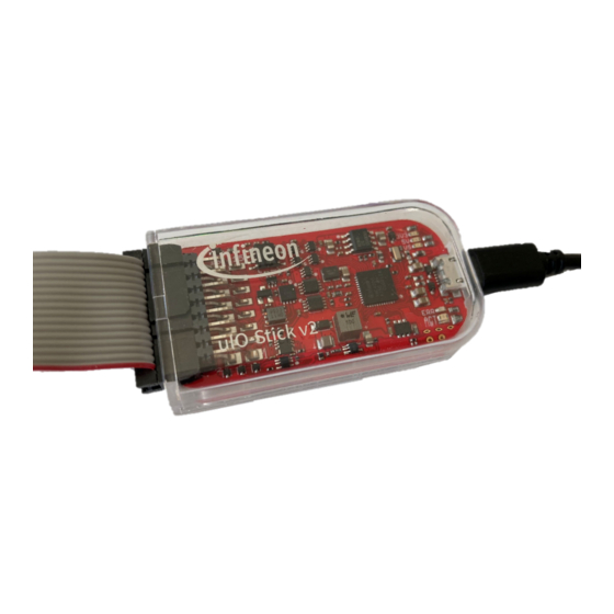
Page 5: Overview
PC. It offers a USB connection to the PC, and several different functionalities, for example SPI, CAN, and GPIOs. The uIO-Stick v2 registers as an HID on the PC, so no driver installation is needed. Figure 1 uIO-Stick v2... - Page 6 User guide 1 Overview Figure 2 uIO-Stick v2 block diagram User guide Rev. 1.00 2023-05-30...
-
Page 7: Hardware Connection
2 Hardware connection Hardware connection The uIO-Stick v2 can be connected to the user PC via USB. For this purpose, it has a micro-USB socket. A micro-USB cable is not included in the packaging. For connection to an embedded device, the uIO-Stick offers several different interfaces available on a 16-pin header. -
Page 8: Comparison Of Uio-Stick And Uio-Stick V2
User guide 3 Comparison of uIO-Stick and uIO-Stick v2 Comparison of uIO-Stick and uIO-Stick v2 The following table gives a comparison between uIO-Stick and uIO-Stick v2. Table 3 Feature uIO-Stick uIO-Stick v2 Connection to PC USB-A plug Micro-USB socket... -
Page 9: Software
User guide 4 Software Software For detailed information about software supported by uIO-Stick v2, please visit www.infineon.com/uio-v2. User guide Rev. 1.00 2023-05-30... -
Page 10: Acronyms
User guide 5 Acronyms Acronyms The following acronyms and terms are used within this document. Table 4 Acronyms Acronyms Name Controller area network CANH Controller area network high CANL Controller area network low Clock Chip select Ground GPIO... -
Page 11: Revision History
User guide Revision history Revision history Document Date of Description of changes version release Rev. 1.00 2023-05-30 Initial document release User guide Rev. 1.00 2023-05-30... -
Page 12: Disclaimer
Infineon Technologies, All Rights Reserved. of any kind, including without limitation warranties of Infineon Technologies’ products may not be used in non-infringement of intellectual property rights of any any applications where a failure of the product or third party.
Need help?
Do you have a question about the uIO-Stick v2 and is the answer not in the manual?
Questions and answers