Table of Contents
Advertisement
Quick Links
Advertisement
Table of Contents

Subscribe to Our Youtube Channel
Summary of Contents for Kobold DW Series
- Page 1 KOBOLD DW SERIES FLOWMETER User Instructions KOBOLD Instruments Canada Inc. KOBOLD Instruments Inc. 9A Aviation 1801 Parkway View Drive Point Claire, QC H9R 4Z2 Pittsburgh, PA 15205 514-428-8090 Fax 514-428-8899 412-788-2830 Fax 412-788-4890 www.koboldusa.com DW_manual_3-04...
-
Page 3: Table Of Contents
Table of Contents General ....................Specifications ..................Installation Instructions................Operation ....................Adjusting the Setpoint ............... Maintenance ..................Arrival of Damaged Equipment .............. Need Help With Your DW ................ List of Diagrams Diagram 1.5 Function Diagram ............Diagram 2.3 Electrical Connections ..........Diagram 2.5 Wiring Diagram &... -
Page 5: General
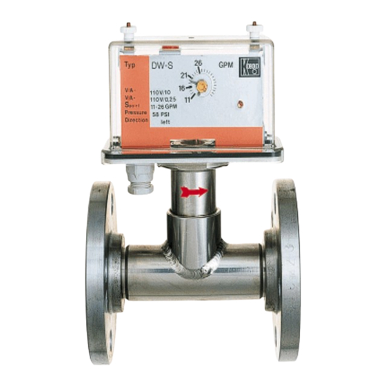
General The KOBOLD DW flowmeters and switches are intended for use in monitoring and measuring (DWU only) control applications involving high flow rates and/or dirty media. The DWS and DWP versions monitor flow rate through a setpoint feature. At setpoint, an internal microswitch is activated, allowing control of other equipment. -
Page 6: Specifications
(the other side), will result in a change of the bellows' spring constant. It is important, therefore, that the DW series be used only at their intended operating pressure if accurate flow readings are desired. -
Page 7: Diagram 2.3 Electrical Connections
Table 2.2; Material Combination & Operating Limits Material Combination Component 0200 0300 T-Piece Brass 316-Ti SS Paddle Brass 303 SS Bellows 316-Ti SS 316-Ti SS Housing: Measuring Section Matte Aluminum Housing: Cover Clear Polycarbonate Flanges (on Flanged Units) Galvanized Steel 316 SS Maximum Operating Pressure 145 PSIG... -
Page 8: Table 2.4 Microswitch Data
Table 2.4; Microswitch Data Quantity: 1 or 2 SPDT Switch Hysteresis: +/- 10% Maximum Load: 10 A/250 V, 2500 VA maximum Status Lamp Power Supply: 220 VAC, or 110 VAC, or 24 VDC Diagram 2.5 Wiring Diagram for DWU Series with 4-Wire 4-20 mA Transmitter/ LCD Display SPDT Relays (optional) are connected at KL1 Power and Analog output are connected at KL2... -
Page 9: Diagram 2.5 Wiring Diagram & Specifications For Dwu W/ 4-20Ma 4 Diagram 2.6 Dimensions
Diagram 2.6; Dimensions FM Rev 03/04... -
Page 10: Installation Instructions
For safety reasons, please read the cautionary information located at the end of the manual, before attempting installation. The KOBOLD DW series meters and switches are to be installed in the orientation described by the symbol on the identification tag. (See Symbol Key, Diagram 3.1). In general, the DW series may be installed in any desired position. -
Page 11: Operation
After welding, make sure that the interior of the weld joint is clean and no metal protrudes. This will ensure that the paddle can move freely after mounting. A tight flange to flange seal is obtained through the use of the supplied rubber gasket. -
Page 12: Maintenance
Maintenance Due to its construction, a paddle type flowmeter, such as the DW series, is nearly maintenance-free. There are only two areas that could (potentially) be a source of concern if the medium contains minerals which could precipitate out onto the instrument. - Page 13 Caution PLEASE READ THE FOLLOWING GENERAL FLOW METER/ MONITOR WARNINGS BEFORE ATTEMPTING INSTALLATION OF YOUR NEW DEVICE. FAILURE TO HEED THE INFORMATION HEREIN MAY RESULT IN EQUIPMENT FAILURE AND POSSIBLE SUBSEQUENT PERSONAL INJURY. FM Rev 03/04...
-
Page 14: Diagram
If using other media, especially corrosive ones, it is critically important that the user determine chemical compatibility with our instruments. A list, detailing material composition of our instruments, is available from KOBOLD Instruments Inc. upon request. KOBOLD Instruments Inc. cannot accept responsibility for failure and consequences resulting from use of media other than water, mineral oil, air, and nitrogen. - Page 15 • During operation, there are a number of situations to avoid: a. The sudden cessation of fluid flow causes what is typically referred to as "water hammer". Most people are familiar with this phenomenon from their home experience - it is the cause behind the loud clank of water pipes which occurs when faucets are turned off too suddenly.


Need help?
Do you have a question about the DW Series and is the answer not in the manual?
Questions and answers