Table of Contents
Advertisement
Quick Links
Advertisement
Table of Contents

Related Manuals for SEFRAM MW3366


Summary of Contents for SEFRAM MW3366
- Page 1 USER MANUAL MW3366 600A TRMS AC+DC CLAMP METER...
- Page 2 1) SAFETY This manual contains information and warnings that must be followed for operating the meter safely and maintaining the meter in a safe operating condition. If the meter is used in a manner not specified by the manufacturer, the protection provided by the meter may be impaired.
-
Page 3: International Symbols
INTERNATIONAL SYMBOLS Marking of Electrical and Electronic Equipment (EEE). Do not dispose of this product as unsorted municipal waste. Contact a qualified recycler. Refer to the explanation in this Manual. Possibility of electric shock Earth (Ground) Meter protected throughout by Double Insulation or Reinforced insulation Fuse Direct Current (DC) Alternating Current (AC) -
Page 4: Product Description
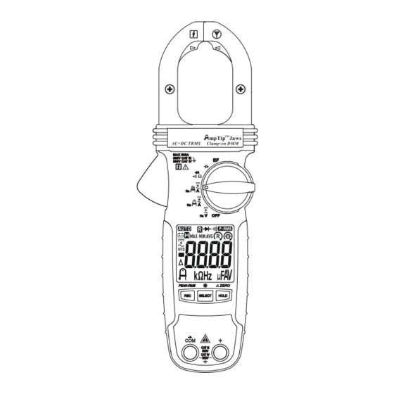
3) PRODUCT DESCRIPTION 1) Antenna area for Non-Contact EF-Detection 2) Jaw center indicator (with DCA polarity), at where best current accuracy is specified 3) Rotary Selector to turn the power ON/OFF and Select a function 4) 3-5/6 digits 6000 counts numeric LCD display 5) Input Jack for all functions EXCEPT... -
Page 5: Operation
4) OPERATION WARNING: Before and after hazardous voltage measurements, test the voltage function on a known source such as line voltage to determine proper meter functioning. ACV, DCV, DC+ACV, & Line-level Hz functions Inputs are made through the test lead terminals COM/+. Defaults at ACV* Function. Press SELECT button momentarily to select DCV, DC+ACV or Line-level Hz function in sequence. - Page 6 Electric Field EF-Detection The meter displays “EF” when it is ready. Signal strength is indicated as a series of bar-graph segments on the display together with variable beep tones. ●Non-Contact EF-Detection: An antenna is located along the top-right end of the stationary clamp jaw, which detects electric field surrounds energized conductors.
- Page 7 NOTES for Non-Invasive (Clamp-on) Current Measurements: NOTE (Application and Removal of the Clamp-on Jaws) For non-invasive current measurements, press the jaw trigger and clamp the jaws around conductor(s) of only one single pole of a circuit for load current measurement. Make sure the jaws are completely closed, or else it will introduce measurement errors.
- Page 8 Non-Invasive AmpTip Low-Current Functions: ACA, DCA, DC+ACA & Hz Input is made via the clamp jaws with best accuracy specified near the jaw tip area for small conductors low-current measurements. Defaults at ACA function. Press SELECT button momentarily to select the subject functions in sequence. Non-Invasive Regular Current Functions: ACA, DCA, DC+ACA, &...
- Page 9 Resistance, Continuity, & Diode functions Inputs are made through the test lead terminals COM/+. Defaults at Resistance. Press SELECT button momentarily to select the subject functions in sequence.
- Page 10 NOTE When using Diode test function, normal forward voltage drop (forward biased) for a good silicon diode is between 0.400V to 0.900V. A reading higher than that indicates a leaky diode (defective). A zero reading indicates a shorted diode (defective). An OL indicates an open diode (defective).
- Page 11 2. When using Capacitance function, discharge capacitor(s) before making any measurements. Large value capacitors should be discharged through an appropriate resistance load Hold Hold feature freezes the display for later view. LCD “ ” turns on. Press the HOLD button momentarily to toggle the hold feature. Record mode Press REC button momentarily to activate MAX/MIN/AVG recording mode.
-
Page 12: Maintenance Note
Intelligent Auto-Power-Off (APO) The Auto-Power-off (APO) mode turns the meter off automatically to extend battery life after approximately 32 minutes of no specified activities, where applicable: 1) Rotary switch or push button operations 2) Significant measuring readings of above 8.5% of ranges 3) Non-OL readings for Resistance, Continuity or Diode function 4) Non-zero readings for Hz function 5) Significant movement indication as in Phase Rotation functions... - Page 13 Cleaning and Storage Periodically wipe the case with a damp cloth and mild detergent; do not use abrasives or solvents. If the meter is not to be used for periods of longer than 60 days, remove the batteries and store them separately. Battery replacement The meter uses standard 1.5V AAA Size (IEC R03) battery X 2 Loosen the 2 captive screws from the battery cover case.
- Page 14 Sensing: True RMS Safety: Certified per IEC/EN/CSA_C22.2_No./UL standards: 61010-1 Ed. 3.1, 61010- 2-032 Ed. 4.0, & 61010-031 Ed. 2.0 to Measurement Categories CAT III 600V and CAT IV 300V ac & dc Transient Protection: 6.0kV (1.2/50s surge) Overload Protections: Current & Hz functions via jaws: 600ADC/AAC rms at <400Hz Voltage &...
- Page 15 DC Voltage RANGE Accuracy 600.0V 1.0% + 5d Input Impedance: 10M, 100 pF nominal AC Voltage (with Digital Low-Pass Filter) RANGE Accuracy 50Hz ~ 60Hz 600.0V 1.0% + 5d Input Impedance: 10M, 100 pF nominal DC+AC Voltage (with Digital Low-Pass Filter) RANGE Accuracy DC, 50Hz ~ 60Hz...
- Page 16 Diode Tester RANGE Accuracy 2.000V 1.5% + 5d Test Current: 0.3mA typically Open Circuit Voltage: < 3.5VDC typically AmpTip clamp-on ACA RANGE Accuracy 1) 2) 3) 4) 50Hz ~ 60Hz 60.00A 1.5% + 5d Induced error from adjacent current-carrying conductor: <0.01A/A for Models Specified with Relative Zero mode applied to offset the non-zero residual readings,...
- Page 17 Regular Clamp-on ACA RANGE Accuracy 1) 2) 3) 50Hz ~ 100Hz 60.00A , 600.0A 1.8% + 5d 4) 5) 100Hz ~ 400Hz 60.00A , 600.0A 2.0% + 5d 4) 5) Induced error from adjacent current-carrying conductor: <0.01A/A for Models , Maximum Crest Factor < 2: 1 at full scale & < 4 : 1 at half scale add 10d to the specified accuracy @ <...
- Page 18 Non-Contact EF-Detection Typical Voltage Bar-Graph Indication 20V (tolerance: 10V ~ 36V) 55V (tolerance: 23V ~ 83V) 110V (tolerance: 59V ~ 165V) - - - 220V (tolerance: 124V ~ 330V) - - - - 440V (tolerance: 250V ~ 600V) - - - - - Indication: Bar-graph segments &...
- Page 19 - NOTE -...
-
Page 20: Limited Warranty
SEFRAM’s warranty does not apply to accessories, fuses, fusible resistors, spark gaps, varistors, batteries or any product which, in SEFRAM's opinion, has been misused, altered, neglected, or damaged by accident or abnormal conditions of operation or handling.
Need help?
Do you have a question about the MW3366 and is the answer not in the manual?
Questions and answers