
Related Manuals for Teka LMD 508


Summary of Contents for Teka LMD 508
- Page 1 Operating instructions (Translation of the original operating instructions) TEKA - LMD 508 TEKA Absaug- und Entsorgungstechnologie GmbH, Millenkamp 9, D-48653 Coesfeld, Tel.: +49 2541-84841-0, E-Mail: info@teka.eu, www.teka.eu...
-
Page 2: Table Of Contents
Table of contents 1. General 2. Description of the system elements 2.1. Illustration of the system elements 2.2. Functionality of the system 2.3. Intended use 3. Safety instructions 3.1. Definition of the hazard symbols 3.2. General safety instructions 4. Storage, transport and installation of the device 5. - Page 3 14. Maintenance intervals 14.1. Usage-related maintenance 14.2. General maintenance 14.2.1. Visual inspection of the device 14.2.2. Functional test of the device 14.2.3. Electrical test of the electrical lines and earthing connections BA_LMD-508_220811_EN 11.08.2022...
-
Page 4: General
1. General Congratulations on purchasing the product from TEKA. Our engineers ensure that our devices reflect the state of the art through continuous development. Nevertheless, misuse or misconduct can endanger your safety. Please observe the following for a successful use of the device: Only authorised and instructed personnel can carry out transport, operation, maintenance and repair of the device. -
Page 5: Description Of The System Elements
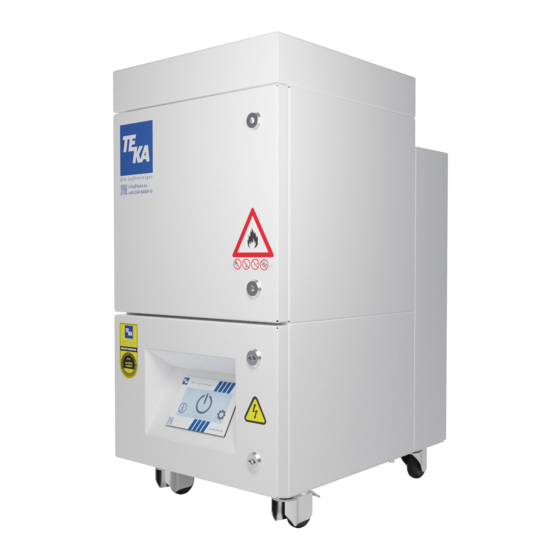
2. Description of the system elements 2.1. Illustration of the system elements Installation example: Z.Nr. 13153705 Pos.1 Operating panel of the control Pos.8 Activated carbon cassette Pos.2 Particle filter housing Pos.9 Suction nozzle Pos.3 Activated carbon housing Pos.10 Exhaust grille Pos.4 Turbine housing Pos.11... -
Page 6: Functionality Of The System
2.2. Functionality of the system The filter unit serves to suck off and filter polluted air (according to the intended use). First of all, the coarse particles are separated at the prefilter mat in the filter section of the unit. The subsequent particle filter cleans even fine smokes and dusts. -
Page 7: Safety Instructions
3. Safety instructions 3.1. Definition of the hazard symbols The device is constructed according to the state of the art and the recognised safety regulations. Nevertheless, during use threats to life and limb of the user or other persons may arise. The impairment of the machine or other property are also possible. -
Page 8: Storage, Transport And Installation Of The Device
4. Storage, transport and installation of the device WARNING Risk of injury from tilting or unmounted components when stored or transported. The device must be secured against tilting and slipping when it is stored or transported. Do not stand under or next to the floating load. Lift trucks, forklift trucks and transport cranes must have a sufficient minimum load bearing capacity. -
Page 9: Connecting An Extraction Element
5.1. Connecting an extraction element For extracting the contaminated air - according to the intended use - the provided extraction element (e.g. suction arm, suction hose, ...) must be connected at the suction nozzle (see chapter 2.1). 5.2. Electrical connection NOTICE Electric malfunction possible in cause of an incorrect power supply. -
Page 10: Operating The System
6. Operating the system 6.1. Explanation of the operating elements Control functions, setting options for programs, menu navigation, error messages, etc. are described in the enclosed operating manual of the unit control. There is also an explanation of the elements of the control panel. 6.2. -
Page 11: Maintenance
7. Maintenance In accordance with national regulations, the operator is obliged to carry out repeat and functional tests. Unless otherwise specified by national regulations, we recommend regular visual inspections and functional tests of the device as described in the chapter “Maintenance intervals”. You find the chapter “Maintenance intervals”... -
Page 12: Reset To Maintenance State
Remove the prefilter mat from the particle filter and dispose of or store it according to the regulations. ● Put a new prefilter mat into the particle filter. Only use TEKA spare filters. Otherwise the proper functioning of the unit is not guaranteed. ● Push the particle filter back into the particle filter housing. -
Page 13: Replacing The Particle Filter
Carefully pull the particle filter (see chapter 2.1) out of the housing. ● Push the new particle filter back into the particle filter housing. Only use TEKA spare filters. Otherwise the proper functioning of the unit is not guaranteed. ●... -
Page 14: Replacing The Activated Carbon
7.4.1. Replacing the activated carbon ● Open the service door of the activated carbon housing (see chapter 2.1). ● Lower the lifting device (A) by turning the clamping screw (B). Therefore, use the hexagon key that is located on the right of the clamping screw. - Page 15 Gradually fill with a number of smaller quantities of activated carbon, spreading it out evenly and gently pressing down on it as you do so. Only use TEKA spare filters. Otherwise the proper functioning of the unit is not guaranteed. ●...
-
Page 16: Replacing The Activated Carbon Cassette
(If a spacer frame is mounted in addition, it must be carefully removed as well.) ● Replace the activated carbon cassette. Only use TEKA spare filters. Otherwise the proper functioning of the unit is not guaranteed. ● Push the filter pack back into the filter housing. Make sure that the filter elements are inserted in the correct order. -
Page 17: Diagnostics And Troubleshooting
A recommissioning of the device must only occur if it is ensured that the system is functionally equivalent to the original state. Repairs may only be carried out by TEKA personnel or, after consultation with TEKA GmbH, by the personnel authorised by the operator. -
Page 18: Technical Data
11. Technical data Supply voltage Frequency Type of current engine power Air flow volume max. m³/h Negative pressure max. 15000 Protection class IP54 ISO class Extraction performance >99 Width Depth Height Weight Sound pressure level dB(A) Allowed ambient temperature °C +5 to +35 (during operations) -10 to +40 (during transport and storage) Max. -
Page 19: Ec Declaration Of Conformity
E-Mail: info@teka.eu Internet: www.teka.eu Designation of the device: TEKA - LMD 508 We hereby declare under our sole responsibility that the product mentioned above, from the serial number A14500010011001 resp. the production number P28000010011001 on, conforms to the following directives:... -
Page 20: Training Protocol
13. Training protocol Designation of the device: TEKA - LMD 508 (This form can be used by the operator to document the training of the employees. Training should be performed by authorized personnel only. Refer to the instructions in Chapter "Safety Instructions") - Page 21 The approach of the maintenance measures is described in chapter "Maintenance". Maintenance interval Maintenance work Chapter recommended by TEKA determined by the operator The saturation of the particle filter is automatically monitored by the filter unit and thus is not subject to a maintenance interval.
- Page 22 14.2.1. Visual inspection of the device Visual inspection: Observation that there are no visible safety-related defects. WARNING Danger arising from the ready to operate condition of the device. Follow the procedure as described in the chapter “Set to maintenance state”. The following steps must be carried out in the course of the visual inspection: ●...
- Page 23 14.2.3. Electrical test of the electrical lines and earthing connections WARNING Danger arising from electricity. The operator is responsible for ensuring that all work on electric components is carried out by authorised and qualified personnel. The device is subject to regular electrical checks by the operator of the device, and are subject to national standards of the different countries.
Need help?
Do you have a question about the LMD 508 and is the answer not in the manual?
Questions and answers