
Related Manuals for Teka DusToo


Summary of Contents for Teka DusToo
- Page 1 Operating instructions (Translation of the original operating instructions) DusToo TEKA Absaug- und Entsorgungstechnologie GmbH, Millenkamp 9, D-48653 Coesfeld, Tel.: +49 2541-84841-0, E-Mail: info@teka.eu, www.teka.eu...
-
Page 2: Table Of Contents
Table of contents 1. General 2. Description of the system elements 2.1. Illustration of the system elements 2.2. Functionality of the system 2.3. Intended use 3. Safety instructions 3.1. Definition of the hazard symbols 3.2. General safety instructions 4. Storage, transport and installation of the device 5. - Page 3 13. Training protocol 14. Maintenance intervals 14.1. Usage-related maintenance 14.2. General maintenance 14.2.1. Visual inspection of the device 14.2.2. Functional test of the device 14.2.3. Electrical test of the electrical lines and earthing connections BA_DusToo_210816_EN 11.01.2022...
-
Page 4: General
1. General Congratulations on purchasing the product from TEKA. Our engineers ensure that our devices reflect the state of the art through continuous development. Nevertheless, misuse or misconduct can endanger your safety. Please observe the following for a successful use of the device: Only authorised and instructed personnel can carry out transport, operation, maintenance and repair of the device. -
Page 5: Description Of The System Elements
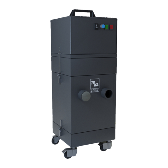
2. Description of the system elements 2.1. Illustration of the system elements Installation example: Z.Nr. 12473703 Pos.1 Filter housing Pos.8 Clock generator Pos.2 Cleaning housing Pos.9 Connection for compressed air Pos.3 Turbine housing Pos.10 Swivel castor Pos.4 Cover plate Pos.11 Dust collecting tank Pos.5 Suction nozzle... -
Page 6: Functionality Of The System
2.2. Functionality of the system The filter unit serves to suck off and filter polluted air (according to the intended use). The air is purified on the surface of the filter cartridge in the filter section of the unit. The separated dust is collected in a dust collecting tank. -
Page 7: Safety Instructions
3. Safety instructions 3.1. Definition of the hazard symbols The device is constructed according to the state of the art and the recognised safety regulations. Nevertheless, during use threats to life and limb of the user or other persons may arise. The impairment of the machine or other property are also possible. -
Page 8: Storage, Transport And Installation Of The Device
WARNING Dangers arising from electricity. The operator must ensure that electrical plants and equipment are only built, modified and maintained by a qualified electrician or under the direction and supervision of a qualified electrician. Do not work on components if you are not sure that these are disconnected. If necessary, disconnect the device from the electric power supply and secure it against unauthorized restarting. -
Page 9: Commissioning
5. Commissioning WARNING Dangers arising from a defective condition of the unit. Make sure that the measures described in this chapter are completed before the commissioning of the unit. All doors of the unit must be closed and all necessary connections must be attached before turning the unit on. -
Page 10: Connecting The Compressed Air Supply
5.3. Connecting the compressed air supply NOTICE The compressed air must be dry and oil-free. According to ISO 8573-1:2010 the compressed air quality must at least meet: [7:4:4] ➔ Partikle size: <40µm ➔ Pressure dew point: <= +3°C ➔ Oil content: <=5mg/m³ 5.3.1. -
Page 11: Operating The System
6. Operating the system 6.1. Explanation of the operating elements Operating elements for the device control Representa Designation Description / function tion ON-OFF-switch By means of this switch, the device is switched on and off. When the device is switched off, it is not disconnected from the power supply. -
Page 12: Setting The Automatic Filter Cartridge Cleaning
6.2. Setting the automatic filter cartridge cleaning The filter cartridge is cleaned automatically by means of the pulse generator (see chapter 2.1). For this purpose, a pneumatic cleaning is triggered after a preset time interval. The opening time controls the duration of the valve cleaning. -
Page 13: Maintenance
7. Maintenance In accordance with national regulations, the operator is obliged to carry out repeat and functional tests. Unless otherwise specified by national regulations, we recommend regular visual inspections and functional tests of the device as described in the chapter “Maintenance intervals”. You find the chapter “Maintenance intervals”... -
Page 14: Reset To Maintenance State
7.1. Reset to maintenance state ● Disconnect the compressed air hose of the external compressed air supply from the insert sleeve (see chapter 2.1). ● Empty the compressed air tank by pressing the "TEST" button of the pulse generator three times in a row. -
Page 15: Replacing The Filter Cartridges
● Insert the new filter cartridge and screw it in place. Only use TEKA spare filters. Otherwise the proper functioning of the unit is not guaranteed. ● Put the housing parts back on top of each other. Reconnect the housing parts by means of the toggle levers. -
Page 16: Emptying The Dust Collecting Tank
7.4. Emptying the dust collecting tank The dust collection container must be cleaned after a certain number of operating hours. This range depends on the amount of dust. The filling level has to be proofed at least once a week. CAUTION Whirling up dust is possible due to the polluted filter cartridges. -
Page 17: Dismantling / Disposal
8. Dismantling / Disposal Only authorised personnel may disassemble the machine. WARNING Dangers arising from electricity. Before the dismantling of the machine it has to be disconnected from the power supply and all supply lines. CAUTION Whirling up dust is possible due to the deposited dust. During all work a suitable respiratory protection and protective clothing have to be worn. -
Page 18: Diagnostics And Troubleshooting
A recommissioning of the device must only occur if it is ensured that the system is functionally equivalent to the original state. Repairs may only be carried out by TEKA personnel or, after consultation with TEKA GmbH, by the personnel authorised by the operator. -
Page 19: Technical Data
11. Technical data Supply voltage Frequency Type of current Engine power 2x 0,8 Air flow volume max. m³/h Negative pressure max. 20.000 Protection class IP54 ISO class Extraction performance > 99 Width Depth Height Weight Sound pressure level dB(A) Allowed ambient temperature °C +5 to +35 (during operations) -10 to +40 (during transport and storage) -
Page 20: Ec Declaration Of Conformity
This declaration will become void if the device is exposed to modifications that are not approved by the manufacturer in written form. Authorized representative for the technical documentation: TEKA Absaug- und Entsorgungstechnologie GmbH, Millenkamp 9, D-48653 Coesfeld (Jürgen Kemper, managing director) Coesfeld, 3rd january 2018 BA_DusToo_210816_EN 11.01.2022... -
Page 21: Training Protocol
13. Training protocol Designation of the device: DusToo (This form can be used by the operator to document the training of the employees. Training should be performed by authorized personnel only. Refer to the instructions in Chapter "Safety Instructions") By his signature, the employee confirms that he has been instructed regarding the following items:... -
Page 22: Maintenance Intervals
The approach of the maintenance measures is described in chapter "Maintenance". Maintenance interval Maintenance work Chapter recommended by TEKA determined by the operator The cleaning of the filter cartridges is automatically carried out Cleaning the filter cartridges by the filter unit and thus is not subject to a maintenance interval. -
Page 23: Visual Inspection Of The Device
14.2.1. Visual inspection of the device Visual inspection: Observation that there are no visible safety-related defects. WARNING Danger arising from the ready to operate condition of the device. Follow the procedure as described in the chapter “Set to maintenance state”. The following steps must be carried out in the course of the visual inspection: ●... -
Page 24: Electrical Test Of The Electrical Lines And Earthing Connections
14.2.3. Electrical test of the electrical lines and earthing connections WARNING Danger arising from electricity. The operator is responsible for ensuring that all work on electric components is carried out by authorised and qualified personnel. The device is subject to regular electrical checks by the operator of the device, and are subject to national standards of the different countries.
Need help?
Do you have a question about the DusToo and is the answer not in the manual?
Questions and answers