Table of Contents
Advertisement
Quick Links
A l l t e s t I n s t r u me n t s , I n c .
5 0 0 C e n t r a l A v e .
F a r mi n g d a l e , N J 0 7 7 2 7
P : ( 7 3 2 ) 9 1 9 - 3 3 3 9
F : ( 7 3 2 ) 9 1 9 - 3 3 3 2
a l l t e s t . n e t
s s a l e s @ a l l t e s t . n e t
T h e t e s t & me a s u r e me n t
e q u i p me n t y o u n e e d a t
t h e p r i c e y o u w a n t .
A l l t e s t c a r r i e s t h e w o r l d ' s l a r g e s t s e l e c t i o n o f
u s e d / r e f u r b i s h e d b e n c h t o p t e s t & me a s u r e me n t
e q u i p me n t a t 5 0 % t h e p r i c e o f n e w .
O O u r e q u i p me n t i s g u a r a n t e e d w o r k i n g , w a r r a n t i e d , a n d
a v a i l a b l e w i t h c e r t i f i e d c a l i b r a t i o n f r o m o u r i n - h o u s e s t a f f
o f t e c h n i c i a n s a n d e n g i n e e r s .
• 1 0 + f u l l t i me t e c h n i c i a n s w i t h o v e r 1 5 0 y e a r s o f
s p e c i a l i z a t i o n
• 9 0 d a y w a r r a n t y & 5 d a y r i g h t o f r e t u r n o n a l l
e q u i p me n t
• • 1 - 3 y e a r w a r r a n t i e s f o r n e w a n d
p r e mi u m- r e f u r b i s h e d e q u i p me n t
• E v e r y u n i t t e s t e d t o O E M s p e c i f i c a t i o n s
• S a t i s f a c t i o n g u a r a n t e e d
Y o u h a v e p l a n s , w e w i l l h e l p y o u a c h i e v e t h e m.
A n y p r o j e c t . A n y b u d g e t .
t
G e t a q u o t e t o d a y !
C C a l l ( 7 3 2 ) 9 1 9 - 3 3 3 9 o r e ma i l s a l e s @a l l t e s t . n e t .
Advertisement
Table of Contents

Subscribe to Our Youtube Channel
Related Manuals for Tektronix DPO3PWR


Summary of Contents for Tektronix DPO3PWR
- Page 1 T h e t e s t & me a s u r e me n t e q u i p me n t y o u n e e d a t t h e p r i c e y o u w a n t . A l l t e s t I n s t r u me n t s , I n c .
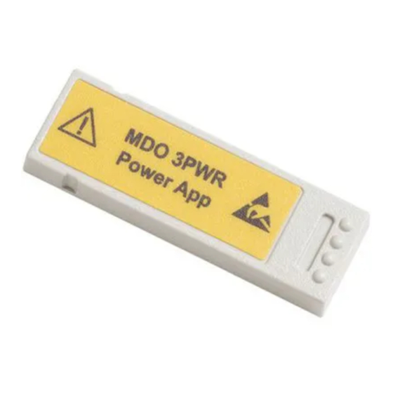
- Page 2 DPO3PWR, MDO3PWR and DPO4PWR Power Analysis Modules User Manual *P071263101* 071-2631-01...
- Page 4 DPO3PWR, MDO3PWR and DPO4PWR Power Analysis Modules User Manual www.tektronix.com 071-2631-01...
- Page 5 Copyright © Tektronix. All rights reserved. Licensed software products are owned by Tektronix or its subsidiaries or suppliers, and are protected by national copyright laws and international treaty provisions. Tektronix products are covered by U.S. and foreign patents, issued and pending. Information in this publication supersedes that in all previously published material.
-
Page 6: Table Of Contents
Making dI/dt and dV/dt Measurements....................Index DPO3PWR, MDO3PWR and DPO4PWR Power Analysis Modules User Manual... - Page 7 Table of Contents DPO3PWR, MDO3PWR and DPO4PWR Power Analysis Modules User Manual...
-
Page 8: General Safety Summary
Observe all terminal ratings. To avoid fire or shock hazard, observe all ratings and markings on the product. Consult the product manual for further ratings information before making connections to the product. DPO3PWR, MDO3PWR and DPO4PWR Power Analysis Modules User Manual... - Page 9 Do not operate in an explosive atmosphere. Keep product surfaces clean and dry. Provide proper ventilation. Refer to the manual's installation instructions for details on installing the product so it has proper ventilation. DPO3PWR, MDO3PWR and DPO4PWR Power Analysis Modules User Manual...
- Page 10 DANGER indicates an injury hazard immediately accessible as you read the marking. WARNING indicates an injury hazard not immediately accessible as you read the marking. CAUTION indicates a hazard to property including the product. DPO3PWR, MDO3PWR and DPO4PWR Power Analysis Modules User Manual...
- Page 11 General safety summary The following symbol(s) may appear on the product: DPO3PWR, MDO3PWR and DPO4PWR Power Analysis Modules User Manual...
-
Page 12: Preface
Preface Preface This manual describes operation of the DPO3PWR, MDO3PWR and DPO4PWR Power Analysis Modules, which enable automatic measurement of many common power measurements in the areas of power quality, harmonics, slew rate, switching loss, safe operating area, ripple, and modulation analysis. - Page 13 Preface viii DPO3PWR, MDO3PWR and DPO4PWR Power Analysis Modules User Manual...
-
Page 14: Installing The Application Module
MDO3000 Series oscilloscopes with firmware version 1.10 or higher and the MDO3PWR application module installed. MSO3000 Series oscilloscopes with firmware version 2.06 or higher and the DPO3PWR application module installed. DPO3000 Series oscilloscopes with firmware version 1.10 or higher and the DPO3PWR application module installed. -
Page 15: Ratings
TCP0150 probe Current probe: Rated 150 A maximum (CAT II) See the user manuals for these products to obtain more detailed specifications. You can find copies of Tektronix user manuals at: www.tektronix.com/manuals DPO3PWR, MDO3PWR and DPO4PWR Power Analysis Modules User Manual... - Page 16 CAT II measurements. Over-voltage categories are defined as follows: CAT II: Local level mains, appliances, portable equipment CAT I: Signal level, special equipment or parts of equipment, telecommunications, electronics DPO3PWR, MDO3PWR and DPO4PWR Power Analysis Modules User Manual...
-
Page 17: Inserting The Application Module Key
Installing the Application Module Inserting the Application Module Key To install a DPO3PWR, MDO3PWR or DPO4PWR application module in a compatible oscilloscope, follow these steps. Basic Installation Observe ESD precautions 1. To avoid damage to the oscilloscope or the application module, observe proper electrostatic discharge (ESD) precautions. - Page 18 1.10 or higher DPO3000 Series 1.10 or higher MSO3000 Series 2.06 or higher For further information on general set up of the oscilloscope, please refer to the appropriate Series Oscilloscope User Manual. DPO3PWR, MDO3PWR and DPO4PWR Power Analysis Modules User Manual...
- Page 19 6. Power on the oscilloscope. If the oscilloscope still does not show the application menu item, you have a problem with the application module or the module slot. Contact the nearest Tektronix service center to resolve the problem. DPO3PWR, MDO3PWR and DPO4PWR Power Analysis Modules User Manual...
-
Page 20: Getting Started
Wait until the display appears. 2. Connect your probes to the oscilloscope, if not already done. For power measurements, typically insert the voltage probe into channel 1 and the current probe into channel 2. DPO3PWR, MDO3PWR and DPO4PWR Power Analysis Modules User Manual... - Page 21 Getting Started 3. Push Default Setup to put the oscilloscope in a known state. 4. Push channel 2 to activate that channel. 5. Push Autoset. DPO3PWR, MDO3PWR and DPO4PWR Power Analysis Modules User Manual...
- Page 22 Choose among power quality, switching loss, harmonics, ripple, modulation, safe operating area, and deskew. For further information on general set up of the oscilloscope, refer to the appropriate Series Oscilloscopes User Manual. DPO3PWR, MDO3PWR and DPO4PWR Power Analysis Modules User Manual...
-
Page 23: Deskewing Probes
Using a Deskew Fixture The following sample procedure assumes use of the deskew procedure built into the Power Analysis module, the Tektronix MDO4000, MSO4000, DPO4000, MDO3000, MSO3000 or DPO3000 Series Oscilloscope, the TCP0030A Current Probe, the P5205A Differential Probe, the TPA-BNC Adapter, the TEK-DPG Deskew Pulse Generator, and 067-1686-XX Power Measurement Deskew &... - Page 24 6. Push the range menu button on the current probe body to set the range values as desired. DPO3PWR, MDO3PWR and DPO4PWR Power Analysis Modules User Manual...
- Page 25 fixture. Make sure to close and lock the current probe slider. 9. Connect the P5205A probe tip and ground lead to the pins on the deskew fixture, as shown at the right. DPO3PWR, MDO3PWR and DPO4PWR Power Analysis Modules User Manual...
- Page 26 11. Push the 2 button to activate channel 2. 12. Push Autoset. 13. Push Test. 14. Push Analysis. Application Analysis None 15. Use the side-bezel buttons to select the function labeled Deskew. DPO3PWR, MDO3PWR and DPO4PWR Power Analysis Modules User Manual...
- Page 27 This shows a sample waveform after deskew. NOTE. For more information on use of the deskew and calibration fixture, refer to the 067-1686-XX Power Measurement Deskew & Calibration Fixture Instructions. It is available for download from www.tektronix.com/manuals. DPO3PWR, MDO3PWR and DPO4PWR Power Analysis Modules User Manual...
- Page 28 Other, and push the side-bezel Propagation Delay button and dial in its propagation delay with multipurpose knob a. To set the deskew value of each channel to the recommended value, push the side-bezel Set all deskews to recommended value button. DPO3PWR, MDO3PWR and DPO4PWR Power Analysis Modules User Manual...
- Page 29 The oscilloscope will automatically recognize many Probe Model Tektronix probes. If your probe is not on the list, Other select Other and manually input the propagation value, as shown below. The oscilloscope will fill in the default values for...
-
Page 30: Measuring Power Quality
Use the power quality functions to view a table of measurement and statistics to check the general power quality in your test circuit. Sample power quality screen shot Sample power quality instrument setup DPO3PWR, MDO3PWR and DPO4PWR Power Analysis Modules User Manual... - Page 31 3. Push Meas. Display to choose which of the 10 power quality measurements to display. 4. Push Frequency Reference to determine the source for the zero crossings for all Power Quality measurements and for frequency. DPO3PWR, MDO3PWR and DPO4PWR Power Analysis Modules User Manual...
- Page 32 1.414 for a pure sine wave and 1.0 for a 50% duty Crest Factor cycle square wave. Frequency The frequency is measured on the frequency source. The unit of measure is hertz (Hz). DPO3PWR, MDO3PWR and DPO4PWR Power Analysis Modules User Manual...
- Page 33 Apparent power value = V The unit of measure is Volt-Amperes or VA. Reactive power The reactive power in Volt-Amp Reactive. Reactive power = V * sine (phase angle). The unit of measure is VAR. DPO3PWR, MDO3PWR and DPO4PWR Power Analysis Modules User Manual...
- Page 34 The angle (0° to 180°) whose cosine is the true power factor. Operating Tips The power measurements in this menu are based on all the complete cycles found in the voltage waveform record. DPO3PWR, MDO3PWR and DPO4PWR Power Analysis Modules User Manual...
-
Page 35: Measuring Switching Loss
WARNING. To prevent electrical shock, always verify that the probe reference point is at ground potential before connecting the probe ground (reference) lead. DPO3PWR, MDO3PWR and DPO4PWR Power Analysis Modules User Manual... - Page 36 Measuring Switching Loss Sample switching loss screen shot Sample switching loss instrument setup DPO3PWR, MDO3PWR and DPO4PWR Power Analysis Modules User Manual...
- Page 37 2 as a current source. 3. Press Reference Levels to choose how to make the switching loss measurements. 4. Press Conduction Calculation to set the method for calculating the conduction loss. DPO3PWR, MDO3PWR and DPO4PWR Power Analysis Modules User Manual...
- Page 38 5. Press Meas. Display to set which of the available switching loss measurements to display. The choices are Power Loss, Energy Loss, or All (both Power and Energy Loss). DPO3PWR, MDO3PWR and DPO4PWR Power Analysis Modules User Manual...
- Page 39 Switching loss measurements are made on each individual complete cycle within the selected region of the acquisition (the entire waveform, by default) and the statistics of those measurements are accumulated across the acquisition, but not between acquisitions. DPO3PWR, MDO3PWR and DPO4PWR Power Analysis Modules User Manual...
-
Page 40: Measuring Harmonics
Select Harmonics to bring up the Harmonics menu. The oscilloscope will display the frequency spectrum of the source waveform and the associated measurement values. First 10 harmonics shown graphically First 10 harmonics shown textually DPO3PWR, MDO3PWR and DPO4PWR Power Analysis Modules User Manual... - Page 41 To prevent electrical shock, always verify that the probe reference point is at ground potential before connecting the probe ground (reference) lead. To Measure Harmonics, Follow These Steps: 1. Select the Harmonics feature from the side menu. (See page 7, Getting Started.) DPO3PWR, MDO3PWR and DPO4PWR Power Analysis Modules User Manual...
- Page 42 If you selected IEC 61000-3-2 or MIL-STD-1399 in a previous menu item, use this item to further define what configuration of these standards you wish to measure. DPO3PWR, MDO3PWR and DPO4PWR Power Analysis Modules User Manual...
- Page 43 6. Push Save Meas. to File to save the results to a .csv file. DPO3PWR, MDO3PWR and DPO4PWR Power Analysis Modules User Manual...
-
Page 44: Measuring Ripple
Use ripple to view a table of measurements and statistics for the AC components of the acquired waveform. Ripple is often found on top of a large DC signal. To Measure Ripple, Follow These Steps: 1. Select the Ripple feature from the side menu. (See page 7, Getting Started.) DPO3PWR, MDO3PWR and DPO4PWR Power Analysis Modules User Manual... - Page 45 With Do Vertical Autoset, you can devote much more of the oscilloscope's ADC range to measurement of the desired ripple. 5. Push Set Offset to 0 to remove all vertical offset. DPO3PWR, MDO3PWR and DPO4PWR Power Analysis Modules User Manual...
-
Page 46: Measuring Modulation
Use the modulation function to view a trend plot of a measurement value across the acquired waveform. This is useful for showing the variations in the modulated switching signal. Sample modulation screen shot Sample modulation instrument set up. DPO3PWR, MDO3PWR and DPO4PWR Power Analysis Modules User Manual... - Page 47 4. Push Modulation Type to define what exactly to measure. Choices include: positive pulse width, negative pulse width, period, frequency, positive duty cycle, and negative duty cycle. 5. Push Reference Levels to define where to make the measurement. DPO3PWR, MDO3PWR and DPO4PWR Power Analysis Modules User Manual...
-
Page 48: Measuring Safe Operating Area
The safe operating display shown in these functions is a simple graphical method for monitoring the interactions between voltage and current and determining whether the device exceeds the limits specified in the manufacturer's data sheet for the device. DPO3PWR, MDO3PWR and DPO4PWR Power Analysis Modules User Manual... - Page 49 You can use the side menu items and multipurpose knob a to set the size of the graticule. The x axis typically displays voltage and the y axis displays current. DPO3PWR, MDO3PWR and DPO4PWR Power Analysis Modules User Manual...
- Page 50 5. Push Action on Violation to select whether or not to stop acquisitions on the detection of an error. 6. Push Gating to define where in time to measure the safe operating area. DPO3PWR, MDO3PWR and DPO4PWR Power Analysis Modules User Manual...
-
Page 51: Making Di/Dt And Dv/Dt Measurements
Making dI/dt and dV/dt Measurements Making dI/dt and dV/dt Measurements Use the cursor readouts to measure the slope (rate of change) of signals. Sample dV/dt readout Sample d/dt instrument set up DPO3PWR, MDO3PWR and DPO4PWR Power Analysis Modules User Manual... - Page 52 If you have selected a voltage waveform, the oscilloscope will display the dV/dt measurement. If you have selected a current waveform, the oscilloscope will display the dI/dt measurement. DPO3PWR, MDO3PWR and DPO4PWR Power Analysis Modules User Manual...
- Page 53 Making dI/dt and dV/dt Measurements DPO3PWR, MDO3PWR and DPO4PWR Power Analysis Modules User Manual...
- Page 54 Switching loss, 22 Deskew, 10 Modulation, 33 Module insertion, 4 dI/dt measurements, 38 dV/dt measurements, 38 Troubleshooting module installation, 6 Power quality, 17 Probe deskew, 10 Equipment list, 1 Harmonics, 27 Ripple, 31 DPO3PWR, MDO3PWR and DPO4PWR Power Analysis Modules User Manual...
Need help?
Do you have a question about the DPO3PWR and is the answer not in the manual?
Questions and answers