Table of Contents
Advertisement
EN
ZERO-TURN MOWER
FR
TONDEUSE À RAYON DE BRAQUAGE ZÉRO
ES
CORTADORA DE CÉSPED DE RADIO DE GIRO CERO
ZTB441/ZTB439/
ZTB501/ZTB520/
ZTB503/ZTB502
commercial.greenworkstools.com
CZ60R24X /CZ52R24X /
CZ48R24X /CZ60R18X /
CZ52R18X/ CZ48R18X /
OPERATOR MANUAL
MANUEL D'OPÉRATEUR
MANUAL DEL OPERADOR
greenworksgear.com
Advertisement
Table of Contents

Related Manuals for GreenWorks Commercial CZ60R24X


Summary of Contents for GreenWorks Commercial CZ60R24X
- Page 1 CZ60R24X /CZ52R24X / CZ48R24X /CZ60R18X / CZ52R18X/ CZ48R18X / ZERO-TURN MOWER OPERATOR MANUAL TONDEUSE À RAYON DE BRAQUAGE ZÉRO MANUEL D’OPÉRATEUR MANUAL DEL OPERADOR CORTADORA DE CÉSPED DE RADIO DE GIRO CERO ZTB441/ZTB439/ ZTB501/ZTB520/ commercial.greenworkstools.com ZTB503/ZTB502 greenworksgear.com...
-
Page 3: Table Of Contents
English 10.3 Slope operation........17 Description........3 11 Operation suggestions..... 18 General information........3 Overview............ 4 12 Electrical system....... 19 General machine safety 12.1 Electrical system safety......19 12.2 Electrical system information....19 warnings........5 12.3 Battery and charger........20 Work area safety........5 12.4 Digital display........... 21 Electrical safety.......... - Page 4 English 19.7 No other warranties........58 19.9 Allocation of risks........58 19.8 Owner's responsibility.......58 19.10Warranty registration........ 58...
-
Page 5: Description
English DESCRIPTION GENERAL INFORMATION This manual applies to the following greenworkscommercial lines: CZ60R24X / CZ52R24X / CZ48R24X / CZ60R18X / CZ52R18X/ CZ48R18X. 1.1.1 TO THE NEW OWNER The purpose of this manual is to assist owners and operators in maintaining and operating this greenworkscommercial mower. -
Page 6: Overview
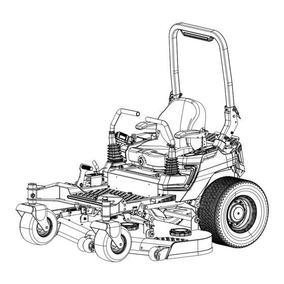
English OVERVIEW ROPS (Roll Over Protective Structure) Steering control levers USB port Cup holder Deck height adjustment lever ETO socket Attachment port Deck Anti-scalp wheels Front wheels Discharge chute Drive wheel LED light Control panel Safety belt Warning light... -
Page 7: General Machine Safety Warnings
English GENERAL MACHINE SAFETY WARNINGS WARNING Read all safety warnings, instructions, illustrations and specifications provided with this machine. Failure to follow all instructions listed below may result in electric shock, fire and/or serious injury. Save all warnings and instructions for future reference. The term "machine"... -
Page 8: Battery Tool Use And Care
English • Do not use the machine if the switch does not turn it on and off Any machine that cannot be controlled with the switch is dangerous and must be repaired. • Disconnect the plug from the power source and/or remove the battery pack, if detachable, from the machine before making any adjustments, changing accessories, or storing the machine. -
Page 9: Safe Practices For Ride-On Mowers
English • Keep guards in place. Guards must be in working order and be properly mounted. A guard that is loose, damaged, or is not functioning correctly may result in personal injury. • Keep all cooling air inlets clear of debris. Blocked air inlets and debris may result in overheating or risk of fire. •... -
Page 10: Children Specific
English CHILDREN SPECIFIC • Tragic accidents can occur if the operator is not alert to the presence of children. Children are often attracted to the machine and the mowing activity. Never assume that children will remain where you last saw them. •... -
Page 11: Symbols On The Product
English SYMBOLS ON THE PRODUCT Some of the following symbols may be used on this tool. Please study them and learn their meaning. Proper interpretation of these symbols will allow you to operate the tool better and safer. - Page 12 English Symbol Name Explanation Recycle Symbols This product use lithium-ion (Li-ion) batteries. Local, state, or federal laws may prohibit disposal of batter- ies in ordinary trash. Consult your local waste authori- ty for information regarding available recycling and/or disposal options. IPX4 Ingress Protection Degree Protection from splashing water.
-
Page 13: Risk Levels
English Symbol Name Explanation Maintain Safety Devices Do not open or remove safety shields while the prod- uct is running. WARNING --- Keep Hands To reduce the risk of injury, keep hands and feet away DANGER/PELIGRO and Feet Away from rotating parts. Do not operate unless discharge KEEP HANDS AND FEET AWAY MANTENGA LAS MANOS Y LOS PIES LEJOS GARDEZ LES MAINS ET LES PIEDS À... -
Page 14: Environmentally Safe Battery Disposal
English ENVIRONMENTALLY SAFE BATTERY DISPOSAL The toxic and corrosive materials below are in the batteries used in this machine: Lithium-ion, a toxic material. WARNING Discard all toxic materials in a specified manner to prevent contamination of the environment. Before discarding damaged or worn-out Lithium-ion battery, contact your local waste disposal agency, or the local Environmental Protection Agency for information and specific instructions. -
Page 15: Know Your Machine
English NOTE KNOW YOUR MACHINE Always drive with both hands. Do not drive with just CONTROL PANEL one hand. The speed buttons (1) are on each side of the steering control levers. Name Function Digital dis- This display shows important electri- play cal system information. -
Page 16: Rops (Roll Over Protective Structure)
English 1. The operator must be in place when testing the operator presence control switch. 2. Press the push button switch with the key fob inserted. 3. Push the steering control levers to the neutral position. 4. Pull the PTO switch ON to engage the motor. 5. -
Page 17: Electric Take Off (Eto) Socket For Connecting Accessories
English rough, uneven terrain. After setting the cutting height, adjust the anti-scalp wheels so they extend below the deck but do not contact the ground. They should always be at least 1/4" to 3/4" below the deck. With the unit sitting on a flat level surface, the wheel position can be adjusted up or down as needed from 3/4"... -
Page 18: Operate The Machine
English 5. Push steering control levers forward for forward motion and pull for reverse motion. NOTE Electric brake will engage after steering control levers are returned to neutral. 10.2.2 DRIVE THE MACHINE After starting the traction drive system, engage the steering control levers and steer as follows: WARNING Always be aware of what is behind the machine before... -
Page 19: Slope Operation
English neutral than the right steering control lever and start • Avoid starting and stopping on a slope. If tires lose the turn. Next, pull back on the steering control traction, disengage the blades and proceed slowly levers until they are past neutral and the machine straight down the slope. -
Page 20: Operation Suggestions
English 5. Grass type, density, and height to mention. Remember to always exercise extreme caution while operating on any slope. 6. Extremely dry conditions • The ROPS may minimize risk of injury or death from 7. Tire pressure rollover. Seat belt must be fastened while operating The attachments mounted to the mower will also a mower equipped with ROPS in the raised and affect the way it handles on a slope. -
Page 21: Electrical System
To avoid this, move onto a previously cut area with the blades engaged. • Charge the battery immediately. Model No. Battery capacity Action Battery capacity Action The working blade will CZ60R24X / stop automatically. The CZ52R24X / The maximum drive unit should immediately CZ48R24X / speed will be 5.5 mph 5%-10% <5%... -
Page 22: Battery And Charger
English 12.3 BATTERY AND CHARGER 12.3.2 CHARGING RECOMMENDATIONS WARNING WARNING Do Not Use An Extension Cord To Charge Mower! Maintenance for the various electrical components If an extension cord must be used, it must have a found on the greenworkscommercial Mower should minimum of 10 AWG wires and be of the shortest only be performed by a greenworkscommercial Mower length possible (10-25 ft long). -
Page 23: Digital Display
English WARNING Cover the battery charging port with the dust cap before operation. 12.4 DIGITAL DISPLAY The function of the digital display, located on the control panel, is to provide electrical system information to the operator. It gives detailed information in the form of pattern, codes and number. - Page 24 English Name Function Name Function 4G GPS Signal Low traction control button. Touch to change to low traction control mode. Security feature is active. Error warning. Touch to check the er- ror code and content. Screen-lock. The touch screen‘s Cutting session. Touch to turn to the CUTTING function is disabled.
- Page 25 English 12.4.3 HOME SCREEN STATE 1. Both driving speed and blade speed have 4 levels. The number of the green icon at each side indicates the driving speed or blade speed at present. 12.4.5 LIGHTS 1. Press the Switch Page Button to turn the digital display to the Lights page as below.
- Page 26 English 4. Touch the Brightness button to enter the Brightness Item Function page. Select your desired screen brightness. Touch Errors This page shows the error con- "X" to exit. tents and suggestions. Statistics This page shows the total work hours, total cut hours, and blade usage time.
-
Page 27: App Operation Tips
English 12.4.8 CHARGING 1. When the vehicle is charging, the digital display will show the charging screen only. It will shows the battery percentage and the estimated time for fully charged. 12.4.7 CUTTING SESSION 1. When the cutting blade is working, the "CUTTING" button will show on the home screen. -
Page 28: Errors
English ERRORS The Canbus system will take action to protect the user and machine when it detects an issue. When it acts to turn off the machine or a component, it will indicate that an error has occurred, and that error will be shown on the digital display. -
Page 29: Bms Error Code
English 14.2 BMS ERROR CODE Error Codes Error Contents User’s Operation Suggestions BMS 11 Battery Discharging Slight Please wait for the battery temperature to cool down, it will disappear Overtemp automatically. BMS 12 Battery Discharging Severe 1. Please restart the vehicle after the battery cools down. Overtemp 2. - Page 30 English Error Codes Error Contents User’s Operation Suggestions BMS 33 Battery Charging Slight The charging current will go down automatically, the error will disappear Overtemp when the battery cools down. BMS 34 Battery Charging Severe 1. Please stop charging. Overtemp 2.
- Page 31 English Error Codes Error Contents User’s Operation Suggestions BMS 56 Battery Charge Contactor 1. Please restart the vehicle. Coil Short 2. Please contact after-sales service. BMS 57 Battery Heating Contactor 1. Please restart the vehicle. Coil Short 2. Please contact after-sales service. BMS 58 Battery Continuous Dis- 1.
-
Page 32: Battery Charger Error Code
English 14.3 BATTERY CHARGER ERROR CODE Error Codes Error Contents User’s Operation Suggestions BC 11 Input Power Undervoltage 1. Please power off the charger to stop charging. 2. Please restart the charger. 3. Please contact after-sales service. BC 12 Input Power Overvoltage 1. -
Page 33: Right Wheel Motor Controller Error Code
English 14.4 RIGHT WHEEL MOTOR CONTROLLER ERROR CODE Error Codes Error Contents User’s Operation Suggestions TR 12 Right Wheel Motor Control- 1. Please reduce the lode. ler Overcurrent 2. Please restart the vehicle. 3. Please check if there is short circuit of the right wheel phase wires U, V and W. - Page 34 English Error Codes Error Contents User’s Operation Suggestions TR 25 Right Wheel Motor Control- 1. Please restart the vehicle. ler Ext 5V Supply Failure 2. Please contact after-sales service. TR 26 Right Wheel Motor Control- 1. Please restart the vehicle. ler Ext 12V Supply Failure 2.
- Page 35 English Error Codes Error Contents User’s Operation Suggestions TR 43 Right Pot2 Wiper High 1. Please check if the right throttle is well connected. 2. Please restart the vehicle. 3. Please contact after-sales service. TR 44 Right Pot2 Throttle Input 1.
- Page 36 English Error Codes Error Contents User’s Operation Suggestions TR 61 GPS Module CAN Commu- 1. Please check if the CAN communication wire on the GPS module is nication Abnormal well connected. 2. Please restart the vehicle. 3. Please contact after-sales service. TR 62 Disable Restart has been Please contact vehicle owner to unlock the vehicle.
- Page 37 English Error Codes Error Contents User’s Operation Suggestions TR 83 Right Wheel Motor Control- 1. Please restart the vehicle. ler Internal Hardware 2. Please contact after-sales service. TR 84 Right Wheel Motor Control- 1. Please restart the vehicle. ler Motor Braking Impaired 2.
- Page 38 English Error Codes Error Contents User’s Operation Suggestions TR A7 Right Wheel Motor Control- 1. Please restart the vehicle. ler Driver 7 Fault 2. Please contact after-sales service. TR A8 Right Wheel Motor Control- 1. Please restart the vehicle. ler Driver Assignment 2.
- Page 39 English Error Codes Error Contents User’s Operation Suggestions TR C8 Right Wheel Motor Control- 1. Please restart the vehicle. ler Invalid CAN Port 2. Please contact after-sales service. TR C9 Right Wheel Motor Control- 1. Please restart the vehicle. ler VCL Watchdog 2.
-
Page 40: Left Wheel Motor Controller Error Code
English 14.5 LEFT WHEEL MOTOR CONTROLLER ERROR CODE Error Codes Error Contents User’s Operation Suggestions TL 12 Left Wheel Motor Controller 1. Please reduce the load. Overcurrent 2. Please restart the vehicle. 3. Please check if there is short circuit of the left wheel phase wires U, V and W. - Page 41 English Error Codes Error Contents User’s Operation Suggestions TL 25 Left Wheel Motor Controller 1. Please restart the vehicle. Ext 5V Supply Failure 2. Please contact after-sales service. TL 26 Left Wheel Motor Controller 1. Please restart the vehicle. Ext 12V Supply Failure 2.
- Page 42 English Error Codes Error Contents User’s Operation Suggestions TL 43 Left Pot2 Wiper High 1. Please check if the left throttle is well connected. 2. Please restart the vehicle. 3. Please contact after-sales service. TL 44 Left Pot2 Throttle Input Ab- 1.
- Page 43 English Error Codes Error Contents User’s Operation Suggestions TL 71 Left Wheel Motor Controller 1. Please restart the vehicle. OS General 2. Please contact after-sales service. TL 72 Left Wheel Motor Controller 1. Please restart the vehicle. PDO Timeout 2. Please contact after-sales service. TL 73 Left Wheel Motor Stall De- 1.
- Page 44 English Error Codes Error Contents User’s Operation Suggestions TL 9A Left Wheel Motor Control- 1. Please restart the vehicle. ler Interlock Braking Super- 2. Please contact after-sales service. vision TL 9B Left Wheel Motor Controller 1. Please restart the vehicle. EMR Supervision 2.
- Page 45 English Error Codes Error Contents User’s Operation Suggestions TL BD Left Wheel Motor Controller 1. Please restart the vehicle. Analog 18 Out Of Range 2. Please contact after-sales service. TL BE Left Wheel Motor Controller 1. Please restart the vehicle. Analog 19 Out Of Range 2.
-
Page 46: Left Blade Motor Controller Error Code
English 14.6 LEFT BLADE MOTOR CONTROLLER ERROR CODE Error Codes Error Contents User’s Operation Suggestions ML 11 Left Blade Motor Controller 1. Please reduce the load. Hardware Overvoltage or 2. Please restart the vehicle. Overcurrent 3. Please check if there is short circuit of left blade motor phase wires U, V and W. - Page 47 English Error Codes Error Contents User’s Operation Suggestions ML 27 Left Blade Motor Control- 1. Please restart the vehicle. ler Temperature Sensor Ab- 2. Please contact after-sales service. normal ML 28 Left Blade Motor Controller 1. Please restart the vehicle. Self-Check Abnormal 2.
-
Page 48: Middle Blade Motor Controller Error Code
English 14.7 MIDDLE BLADE MOTOR CONTROLLER ERROR CODE Error Codes Error Contents User’s Operation Suggestions MM 11 Middle Blade Motor Con- 1. Please reduce the load. troller Hardware Overvolt- 2. Please restart the vehicle. age or Overcurrent 3. Please check if there is short circuit of middle blade motor phase wires U, V and W. - Page 49 English Error Codes Error Contents User’s Operation Suggestions 2. Please contact after-sales service. MM 27 Middle Blade Motor Con- 1. Please restart the vehicle. troller Temperature Sensor 2. Please contact after-sales service. Abnormal MM 28 Middle Blade Motor Con- 1. Please restart the vehicle. troller Self-Check Abnormal 2.
-
Page 50: Right Blade Motor Controller Error Code
English 14.8 RIGHT BLADE MOTOR CONTROLLER ERROR CODE Error Codes Error Contents User’s Operation Suggestions MR 11 Right Blade Motor Control- 1. Please reduce the load. ler Hardware Overvoltage 2. Please restart the vehicle. or Overcurrent 3. Please check if there is short circuit of right blade motor phase wires U, V and W. - Page 51 English Error Codes Error Contents User’s Operation Suggestions MR 27 Right Blade Motor Control- 1. Please restart the vehicle. ler Temperature Sensor Ab- 2. Please contact after-sales service. normal MR 28 Right Blade Motor Control- 1. Please restart the vehicle. ler Self-Check Abnormal 2.
-
Page 52: Attachment Controller Error Code
English 14.9 ATTACHMENT CONTROLLER ERROR CODE Error Codes Error Contents User’s Operation Suggestions AT 11 Attachment Motor Control- 1. Please reduce the load. ler Hardware Overvoltage 2. Please restart the vehicle. or Overcurrent 3. Please check if there is short circuit of attachment motor phase wires U, V and W. -
Page 53: Maintenance
English WARNING MAINTENANCE • The blade sail (curved part) must be pointing Regular maintenance is the best prevention for costly upward toward the inside of the deck to ensure downtime or expensive, premature repair. The following proper cutting. pages contain suggested maintenance information and •... -
Page 54: Torque Values
English torque as shown below, if necessary, and replace WARNING parts that show wear or damage. Check the tire pressure carefully while inflating. Too • Inspect the seat latch to make sure it is secured and much air in the tire could cause the tire to burst, functioning properly. -
Page 55: Service
English to block the unit up. Use in pairs only. Follow the 15.7 SERVICE instructions supplied with the vehicle stands. • Do not touch hot parts of machine. IMPORTANT • Keep nuts and bolts tight, especially the blade Wait for all movement to stop before adjusting, attachment bolts. -
Page 56: Cleaning And Storage
English 5. Immediately after moving the machine, engage the WARNING transmission for operation. Use care when loading or unloading the mower onto a 16.2.2 NEUTRAL BYPASS LEVERS trailer. Ensure the cutting deck is raised to the highest position so that it is not caught on the ramp. The If manual pushing is needed wheels on the mower can go off the ramp or trailer, causing the mower to pivot or tip over, and result in a... -
Page 57: Troubleshooting
English • Inspect the blade and replace it or sharpen it, if • Always keep the batteries fully charged. It is required (refer to the Maintenance section). especially important to prevent battery damage when the temperature is below 32°F (0°C). •... -
Page 58: Technical Data
English TECHNICAL DATA Model No. CZ60R24X CZ52R24X CZ48R24X CZ48R18X CZ52R18X CZ60R18X Gross vehicle weight (lbs) 1600 1567 1549 1529 1496 1478 Length 73.8” 71” 71” 71” 71” 73.8” Height 46.7” 46.7” 46.7” 46.7” 46.7” 46.7” Width (with discharge) 73.5” 65.4”... -
Page 59: Who Must Perform The Warranty Service
English • Lack of proper maintenance; damage caused by improper installation of the battery; neglect, breakage, exposure to extreme temperature conditions including but not limited to freezing temperatures, hot temperatures, proximity to heat sources including warmers or fire, exposure to water or other substances, wreckage, operation of the battery in an overcharged or uncharged condition. -
Page 60: Time Limit
English 19.6 TIME LIMIT Unless State law determines otherwise: Any action for breach of warranty must be commenced within five (5) years or sixty (60) months from the date of purchase in a residential and/or commercial application. In the event the date of manufacture exceeds a reasonable timeframe preceding first customer purchase, greenworkscommercial warranty may be subject to additional limitations. - Page 61 commercial.greenworkstools.com greenworksgear.com P0804570-01 Rev B...
Need help?
Do you have a question about the CZ60R24X and is the answer not in the manual?
Questions and answers